
Page 229 - Materials Science and Engineering An Introduction
P. 229
6.12 Design/Safety Factors • 201
where d is the rod diameter and F is the applied force; furthermore, each of the two rods must
support half of the total force, or 110,000 N (25,000 psi). Solving for d leads to
F
d = 2
7ps w
110,000 N
=
6
2
A p(62 * 10 N/m )
-2
= 4.75 * 10 m = 47.5 mm (1.87 in.)
Therefore, the diameter of each of the two rods should be 47.5 mm, or 1.87 in.
DESIGN EXAMPLE 6.2
Materials Specification for a Pressurized Cylindrical Tube
(a) Consider a thin-walled cylindrical tube having a radius of 50 mm and wall thickness 2 mm
that is to be used to transport pressurized gas. If inside and outside tube pressures are 20 and
0.5 atm (2.027 and 0.057 MPa), respectively, which of the metals and alloys listed in Table 6.8
are suitable candidates? Assume a factor of safety of 4.0.
For a thin-walled cylinder, the circumferential (or “hoop”) stress (s) depends on pres-
sure difference (≤p), cylinder radius (r i ), and tube wall thickness (t) as follows:
r i p
s = (6.25)
t
These parameters are noted on the schematic sketch of a cylinder presented in Figure 6.21.
(b) Determine which of the alloys that satisfy the criterion of part (a) can be used to produce a
tube with the lowest cost.
Solution
(a) In order for this tube to transport the gas in a satisfactory and safe manner, we want to
minimize the likelihood of plastic deformation. To accomplish this, we replace the circum-
ferential stress in Equation 6.25 with the yield strength of the tube material divided by the
factor of safety, N—that is,
s y r i p
=
N t
And solving this expression for s y leads to
Nr i p
s y = (6.26)
t
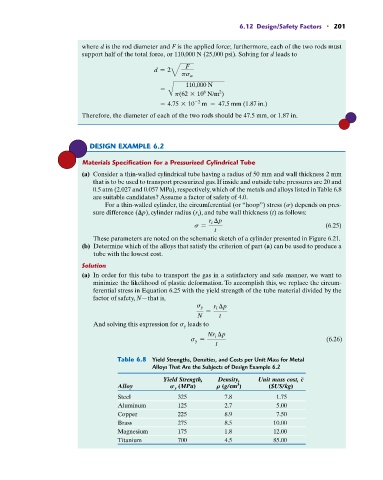
Table 6.8 Yield Strengths, Densities, and Costs per Unit Mass for Metal
Alloys That Are the Subjects of Design Example 6.2
Yield Strength, Density, Unit mass cost, c
3
Alloy S y (MPa) R (g/cm ) ($US/kg)
Steel 325 7.8 1.75
Aluminum 125 2.7 5.00
Copper 225 8.9 7.50
Brass 275 8.5 10.00
Magnesium 175 1.8 12.00
Titanium 700 4.5 85.00