
Page 260 - Materials Science and Engineering An Introduction
P. 260
232 • Chapter 7 / Dislocations and Strengthening Mechanisms
(a) (a)
(b) (b)
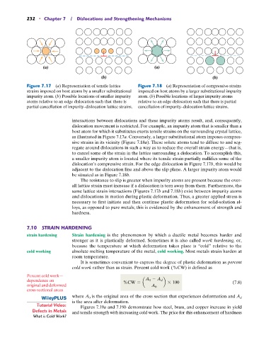
Figure 7.17 (a) Representation of tensile lattice Figure 7.18 (a) Representation of compressive strains
strains imposed on host atoms by a smaller substitutional imposed on host atoms by a larger substitutional impurity
impurity atom. (b) Possible locations of smaller impurity atom. (b) Possible locations of larger impurity atoms
atoms relative to an edge dislocation such that there is relative to an edge dislocation such that there is partial
partial cancellation of impurity–dislocation lattice strains. cancellation of impurity–dislocation lattice strains.
interactions between dislocations and these impurity atoms result, and, consequently,
dislocation movement is restricted. For example, an impurity atom that is smaller than a
host atom for which it substitutes exerts tensile strains on the surrounding crystal lattice,
as illustrated in Figure 7.17a. Conversely, a larger substitutional atom imposes compres-
sive strains in its vicinity (Figure 7.18a). These solute atoms tend to diffuse to and seg-
regate around dislocations in such a way as to reduce the overall strain energy—that is,
to cancel some of the strain in the lattice surrounding a dislocation. To accomplish this,
a smaller impurity atom is located where its tensile strain partially nullifies some of the
dislocation’s compressive strain. For the edge dislocation in Figure 7.17b, this would be
adjacent to the dislocation line and above the slip plane. A larger impurity atom would
be situated as in Figure 7.18b.
The resistance to slip is greater when impurity atoms are present because the over-
all lattice strain must increase if a dislocation is torn away from them. Furthermore, the
same lattice strain interactions (Figures 7.17b and 7.18b) exist between impurity atoms
and dislocations in motion during plastic deformation. Thus, a greater applied stress is
necessary to first initiate and then continue plastic deformation for solid-solution al-
loys, as opposed to pure metals; this is evidenced by the enhancement of strength and
hardness.
7.10 STRAIN HARDENING
strain hardening Strain hardening is the phenomenon by which a ductile metal becomes harder and
stronger as it is plastically deformed. Sometimes it is also called work hardening, or,
because the temperature at which deformation takes place is “cold” relative to the
cold working absolute melting temperature of the metal, cold working. Most metals strain harden at
room temperature.
It is sometimes convenient to express the degree of plastic deformation as percent
cold work rather than as strain. Percent cold work (%CW) is defined as
Percent cold work—
dependence on %CW = a A 0 - A d b * 100 (7.8)
original and deformed A 0
cross-sectional areas
where A 0 is the original area of the cross section that experiences deformation and A d
is the area after deformation.
Tutorial Video: Figures 7.19a and 7.19b demonstrate how steel, brass, and copper increase in yield
Defects in Metals and tensile strength with increasing cold work. The price for this enhancement of hardness
What is Cold Work?