
Page 282 - Materials Science and Engineering An Introduction
P. 282
254 • Chapter 8 / Failure
(a) (b) (c)
Shear
Fibrous
(d) (e)
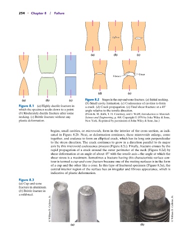
(a) (b) (c) Figure 8.2 Stages in the cup-and-cone fracture. (a) Initial necking.
(b) Small cavity formation. (c) Coalescence of cavities to form
Figure 8.1 (a) Highly ductile fracture in a crack. (d) Crack propagation. (e) Final shear fracture at a 45
which the specimen necks down to a point. angle relative to the tensile direction.
(b) Moderately ductile fracture after some (From K. M. Ralls, T. H. Courtney, and J. Wulff, Introduction to Materials
necking. (c) Brittle fracture without any Science and Engineering, p. 468. Copyright © 1976 by John Wiley & Sons,
plastic deformation. New York. Reprinted by permission of John Wiley & Sons, Inc.)
begins, small cavities, or microvoids, form in the interior of the cross section, as indi-
cated in Figure 8.2b. Next, as deformation continues, these microvoids enlarge, come
together, and coalesce to form an elliptical crack, which has its long axis perpendicular
to the stress direction. The crack continues to grow in a direction parallel to its major
axis by this microvoid coalescence process (Figure 8.2c). Finally, fracture ensues by the
rapid propagation of a crack around the outer perimeter of the neck (Figure 8.2d) by
shear deformation at an angle of about 45 with the tensile axis—the angle at which the
shear stress is a maximum. Sometimes a fracture having this characteristic surface con-
tour is termed a cup-and-cone fracture because one of the mating surfaces is in the form
of a cup and the other like a cone. In this type of fractured specimen (Figure 8.3a), the
central interior region of the surface has an irregular and fibrous appearance, which is
indicative of plastic deformation.
Figure 8.3
(a) Cup-and-cone
fracture in aluminum.
(b) Brittle fracture in
a mild steel.
© William D. Callister, Jr. © William D. Callister, Jr.
(a) (b)