
Page 284 - Materials Science and Engineering An Introduction
P. 284
256 • Chapter 8 / Failure
(a)
(b)
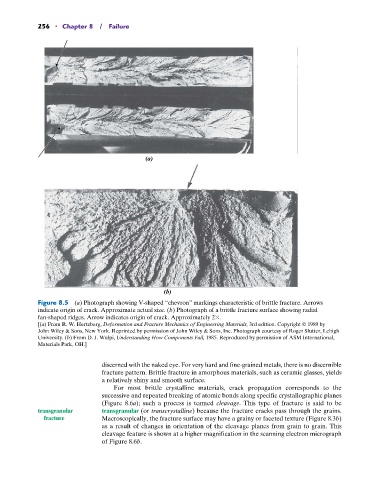
Figure 8.5 (a) Photograph showing V-shaped “chevron” markings characteristic of brittle fracture. Arrows
indicate origin of crack. Approximate actual size. (b) Photograph of a brittle fracture surface showing radial
fan-shaped ridges. Arrow indicates origin of crack. Approximately 2 .
[(a) From R. W. Hertzberg, Deformation and Fracture Mechanics of Engineering Materials, 3rd edition. Copyright © 1989 by
John Wiley & Sons, New York. Reprinted by permission of John Wiley & Sons, Inc. Photograph courtesy of Roger Slutter, Lehigh
University. (b) From D. J. Wulpi, Understanding How Components Fail, 1985. Reproduced by permission of ASM International,
Materials Park, OH.]
discerned with the naked eye. For very hard and fine-grained metals, there is no discernible
fracture pattern. Brittle fracture in amorphous materials, such as ceramic glasses, yields
a relatively shiny and smooth surface.
For most brittle crystalline materials, crack propagation corresponds to the
successive and repeated breaking of atomic bonds along specific crystallographic planes
(Figure 8.6a); such a process is termed cleavage. This type of fracture is said to be
transgranular transgranular (or transcrystalline) because the fracture cracks pass through the grains.
fracture Macroscopically, the fracture surface may have a grainy or faceted texture (Figure 8.3b)
as a result of changes in orientation of the cleavage planes from grain to grain. This
cleavage feature is shown at a higher magnification in the scanning electron micrograph
of Figure 8.6b.