
Page 287 - Materials Science and Engineering An Introduction
P. 287
8.5 Principles of Fracture Mechanics • 259
s
0
r s
t m
a
X X' Stress
2a
x x'
s
0
x x'
s Position along X–X'
0
(a) (b)
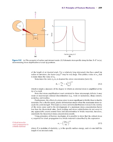
Figure 8.8 (a) The geometry of surface and internal cracks. (b) Schematic stress profile along the line X–X in (a),
demonstrating stress amplification at crack tip positions.
of the length of an internal crack. For a relatively long microcrack that has a small tip
1/2
radius of curvature, the factor (a/r t ) may be very large. This yields a value of s m that
is many times the value of s 0 .
Sometimes the ratio s m /s 0 is denoted the stress concentration factor K t :
a 1/2
s m
K t = = 2a b (8.2)
s 0 r t
which is simply a measure of the degree to which an external stress is amplified at the
tip of a crack.
Note that stress amplification is not restricted to these microscopic defects; it may
occur at macroscopic internal discontinuities (e.g., voids or inclusions), sharp corners,
scratches, and notches.
Furthermore, the effect of a stress raiser is more significant in brittle than in ductile
materials. For a ductile metal, plastic deformation ensues when the maximum stress ex-
ceeds the yield strength. This leads to a more uniform distribution of stress in the vicinity
of the stress raiser and to the development of a maximum stress concentration factor
less than the theoretical value. Such yielding and stress redistribution do not occur to
any appreciable extent around flaws and discontinuities in brittle materials; therefore,
essentially the theoretical stress concentration results.
Using principles of fracture mechanics, it is possible to show that the critical stress
s c required for crack propagation in a brittle material is described by the expression
Critical stress for 2Eg s 1/2 (8.3)
crack propagation in s c = a pa b
a brittle material
where E is modulus of elasticity, g s is the specific surface energy, and a is one-half the
length of an internal crack.