
Page 283 - Materials Science and Engineering An Introduction
P. 283
8.4 Brittle Fracture • 255
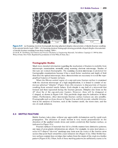
(a) 5 m (b) 4 m
Figure 8.4 (a) Scanning electron fractograph showing spherical dimples characteristic of ductile fracture resulting
from uniaxial tensile loads. 3300 . (b) Scanning electron fractograph showing parabolic-shaped dimples characteristic
of ductile fracture resulting from shear loading. 5000 .
(From R. W. Hertzberg, Deformation and Fracture Mechanics of Engineering Materials, 3rd edition. Copyright © 1989 by John
Wiley & Sons, New York. Reprinted by permission of John Wiley & Sons, Inc.)
Fractographic Studies
Much more detailed information regarding the mechanism of fracture is available from
microscopic examination, normally using scanning electron microscopy. Studies of
this type are termed fractographic. The scanning electron microscope is preferred for
fractographic examinations because it has a much better resolution and depth of field
than does the optical microscope; these characteristics are necessary to reveal the topo-
graphical features of fracture surfaces.
When the fibrous central region of a cup-and-cone fracture surface is examined
with the electron microscope at a high magnification, it is found to consist of nu-
merous spherical “dimples” (Figure 8.4a); this structure is characteristic of fracture
resulting from uniaxial tensile failure. Each dimple is one half of a microvoid that
formed and then separated during the fracture process. Dimples also form on the
45 shear lip of the cup-and-cone fracture. However, these will be elongated or
C-shaped, as shown in Figure 8.4b. This parabolic shape may be indicative of shear
failure. Furthermore, other microscopic fracture surface features are also possible.
Fractographs such as those shown in Figures 8.4a and 8.4b provide valuable informa-
tion in the analyses of fracture, such as the fracture mode, the stress state, and the
site of crack initiation.
8.4 BRITTLE FRACTURE
Brittle fracture takes place without any appreciable deformation and by rapid crack
propagation. The direction of crack motion is very nearly perpendicular to the
direction of the applied tensile stress and yields a relatively flat fracture surface, as
indicated in Figure 8.1c.
Fracture surfaces of materials that fail in a brittle manner have distinctive patterns;
any signs of gross plastic deformation are absent. For example, in some steel pieces, a
series of V-shaped “chevron” markings may form near the center of the fracture cross
section that point back toward the crack initiation site (Figure 8.5a). Other brittle frac-
ture surfaces contain lines or ridges that radiate from the origin of the crack in a fanlike
pattern (Figure 8.5b). Often, both of these marking patterns are sufficiently coarse to be