
Page 289 - Materials Science and Engineering An Introduction
P. 289
8.5 Principles of Fracture Mechanics • 261
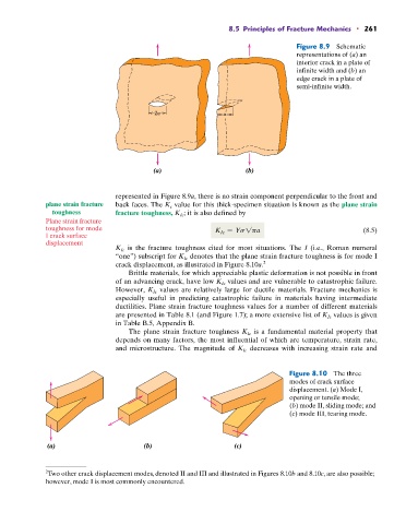
Figure 8.9 Schematic
representations of (a) an
interior crack in a plate of
infinite width and (b) an
edge crack in a plate of
semi-infinite width.
2a a
(a) (b)
represented in Figure 8.9a, there is no strain component perpendicular to the front and
plane strain fracture back faces. The K c value for this thick-specimen situation is known as the plane strain
toughness fracture toughness, K Ic ; it is also defined by
Plane strain fracture
toughness for mode K Ic = Ys1pa (8.5)
I crack surface
displacement
K Ic is the fracture toughness cited for most situations. The I (i.e., Roman numeral
“one”) subscript for K Ic denotes that the plane strain fracture toughness is for mode I
crack displacement, as illustrated in Figure 8.10a. 2
Brittle materials, for which appreciable plastic deformation is not possible in front
of an advancing crack, have low K Ic values and are vulnerable to catastrophic failure.
values are relatively large for ductile materials. Fracture mechanics is
However, K Ic
especially useful in predicting catastrophic failure in materials having intermediate
ductilities. Plane strain fracture toughness values for a number of different materials
are presented in Table 8.1 (and Figure 1.7); a more extensive list of K Ic values is given
in Table B.5, Appendix B.
is a fundamental material property that
The plane strain fracture toughness K Ic
depends on many factors, the most influential of which are temperature, strain rate,
decreases with increasing strain rate and
and microstructure. The magnitude of K Ic
Figure 8.10 The three
modes of crack surface
displacement. (a) Mode I,
opening or tensile mode;
(b) mode II, sliding mode; and
(c) mode III, tearing mode.
(a) (b) (c)
2 Two other crack displacement modes, denoted II and III and illustrated in Figures 8.10b and 8.10c, are also possible;
however, mode I is most commonly encountered.