
Page 290 - Materials Science and Engineering An Introduction
P. 290
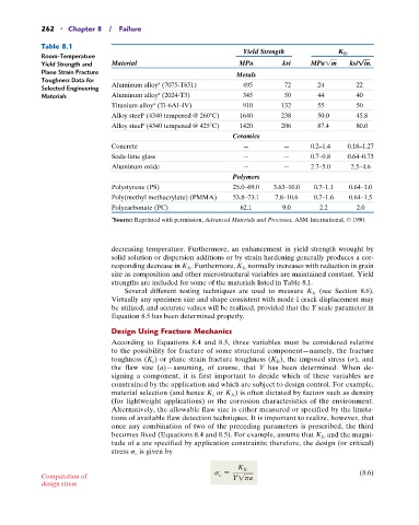
262   •  Chapter 8  /  Failure

            Table 8.1
                                                                    Yield Strength            K Ic
             Room-Temperature
            Yield Strength and   Material                          MPa         ksi    MPa1m      ksi!in.
            Plane Strain Fracture                                 Metals
            Toughness Data for              a
            Selected Engineering   Aluminum alloy  (7075-T651)      495        72       24         22
                                            a
            Materials           Aluminum alloy  (2024-T3)           345        50       44         40
                                Titanium alloy  (Ti-6Al-4V)         910       132       55         50
                                           a
                                Alloy steel  (4340 tempered @ 260 C)  1640    238       50.0       45.8
                                        a
                                Alloy steel  (4340 tempered @ 425 C)  1420    206       87.4       80.0
                                        a
                                                                 Ceramics
                                Concrete                            —          —      0.2–1.4   0.18–1.27
                                Soda-lime glass                     —          —      0.7–0.8   0.64–0.73
                                Aluminum oxide                      —          —      2.7–5.0    2.5–4.6
                                                                 Polymers
                                Polystyrene (PS)                 25.0–69.0   3.63–10.0   0.7–1.1   0.64–1.0
                                Poly(methyl methacrylate) (PMMA)   53.8–73.1   7.8–10.6   0.7–1.6   0.64–1.5
                                Polycarbonate (PC)                 62.1        9.0       2.2       2.0
                                a
                                Source: Reprinted with permission, Advanced Materials and Processes, ASM International, © 1990.


                                decreasing temperature. Furthermore, an enhancement in yield strength wrought by
                                solid solution or dispersion additions or by strain hardening generally produces a cor-
                                responding decrease in K Ic . Furthermore, K Ic  normally increases with reduction in grain
                                size as composition and other microstructural variables are maintained constant. Yield
                                strengths are included for some of the materials listed in Table 8.1.
                                                                                         (see Section 8.6).
                                   Several different testing techniques are used to measure K Ic
                                Virtually any specimen size and shape consistent with mode I crack displacement may
                                be utilized, and accurate values will be realized, provided that the Y scale parameter in
                                Equation 8.5 has been determined properly.
                                Design Using Fracture Mechanics
                                According to Equations 8.4 and 8.5, three variables must be considered relative
                                to the possibility for fracture of some structural component—namely, the fracture
                                toughness (K c ) or plane strain fracture toughness (K Ic ), the imposed stress (s),  and
                                the flaw size (a)—assuming, of course, that Y  has been determined. When de-
                                signing a component, it is first important to decide which of these variables are
                                c onstrained by the application and which are subject to design control. For example,
                                material selection (and hence K c  or K Ic ) is often dictated by factors such as density
                                (for lightweight applications) or the corrosion characteristics of the environment.
                                Alternatively, the allowable flaw size is either measured or specified by the limita-
                                tions of available flaw detection techniques. It is important to realize, however, that
                                once any combination of two of the preceding parameters is prescribed, the third
                                becomes fixed (Equations 8.4 and 8.5). For example, assume that K Ic  and the magni-
                                tude of a are specified by application constraints; therefore, the design (or critical)
                                stress   c  is given by

                                                            s c =  K Ic                             (8.6)
            Computation of                                       Y1pa
            design stress