
Page 295 - Materials Science and Engineering An Introduction
P. 295
8.6 Fracture Toughness Testing • 267
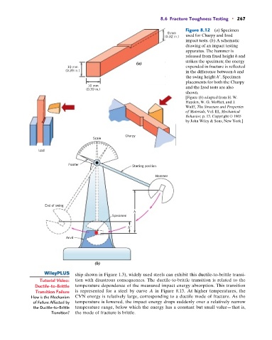
Figure 8.12 (a) Specimen
8 mm
(0.32 in.) used for Charpy and Izod
impact tests. (b) A schematic
drawing of an impact testing
apparatus. The hammer is
released from fixed height h and
strikes the specimen; the energy
(a)
10 mm expended in fracture is reflected
(0.39 in.) in the difference between h and
the swing height h . Specimen
placements for both the Charpy
10 mm and the Izod tests are also
(0.39 in.)
shown.
[Figure (b) adapted from H. W.
Hayden, W. G. Moffatt, and J.
Wulff, The Structure and Properties
of Materials, Vol. III, Mechanical
Behavior, p. 13. Copyright © 1965
by John Wiley & Sons, New York.]
Charpy
Scale
Izod
Pointer Starting position
Hammer
End of swing
h
Specimen
h'
Anvil
(b)
ship shown in Figure 1.3), widely used steels can exhibit this ductile-to-brittle transi-
Tutorial Video: tion with disastrous consequences. The ductile-to-brittle transition is related to the
Ductile-to-Brittle temperature dependence of the measured impact energy absorption. This transition
Transition Failure is represented for a steel by curve A in Figure 8.13. At higher temperatures, the
How is the Mechanism CVN energy is relatively large, corresponding to a ductile mode of fracture. As the
of Failure Affected by temperature is lowered, the impact energy drops suddenly over a relatively narrow
the Ductile-to-Brittle temperature range, below which the energy has a constant but small value—that is,
Transition? the mode of fracture is brittle.