
Page 308 - Materials Science and Engineering An Introduction
P. 308
280 • Chapter 8 / Failure
Case
Shot peened
Stress amplitude region
Core
Normal
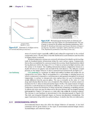
Figure 8.28 Photomicrograph showing both core (bottom) and
carburized outer case (top) regions of a case-hardened steel. The case
Cycles to failure is harder, as attested by the smaller microhardness indentation. 100 .
(logarithmic scale)
(From R. W. Hertzberg, Deformation and Fracture Mechanics of Engineer-
Figure 8.27 Schematic S–N fatigue curves ing Materials, 3rd edition. Copyright © 1989 by John Wiley & Sons, New
for normal and shot-peened steel. York. Reprinted by permission of John Wiley & Sons, Inc.)
stress of external origin is partially nullified and reduced in magnitude by the residual
compressive stress. The net effect is that the likelihood of crack formation and therefore
of fatigue failure is reduced.
Residual compressive stresses are commonly introduced into ductile metals mechan-
ically by localized plastic deformation within the outer surface region. Commercially,
this is often accomplished by a process termed shot peening. Small, hard particles (shot)
having diameters within the range of 0.1 to 1.0 mm are projected at high velocities onto
the surface to be treated. The resulting deformation induces compressive stresses to a
depth of between one-quarter and one-half of the shot diameter. The influence of shot
peening on the fatigue behavior of steel is demonstrated schematically in Figure 8.27.
case hardening Case hardening is a technique by which both surface hardness and fatigue life are
enhanced for steel alloys. This is accomplished by a carburizing or nitriding process by
which a component is exposed to a carbonaceous or nitrogenous atmosphere at elevated
temperature. A carbon- or nitrogen-rich outer surface layer (or case) is introduced by
atomic diffusion from the gaseous phase. The case is normally on the order of 1 mm
deep and is harder than the inner core of material. (The influence of carbon content on
hardness for Fe–C alloys is demonstrated in Figure 10.29a.) The improvement of fatigue
properties results from increased hardness within the case, as well as the desired residual
compressive stresses the formation of which attends the carburizing or nitriding process.
A carbon-rich outer case may be observed for the gear shown in the top chapter-opening
photograph for Chapter 5; it appears as a dark outer rim within the sectioned segment.
The increase in case hardness is demonstrated in the photomicrograph in Figure 8.28.
The dark and elongated diamond shapes are Knoop microhardness indentations. The
upper indentation, lying within the carburized layer, is smaller than the core indentation.
8.11 ENVIRONMENTAL EFFECTS
Environmental factors may also affect the fatigue behavior of materials. A few brief
comments will be given relative to two types of environment-assisted fatigue failure:
thermal fatigue and corrosion fatigue.