Page 304 - Materials Science and Engineering An Introduction
P. 304

276   •  Chapter 8  /  Failure
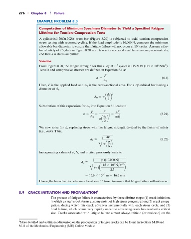
                       EXAMPLE PROBLEM 8.3

                         Computation of Minimum Specimen Diameter to Yield a Specified Fatigue
                         Lifetime for Tension-Compression Tests
                         A cylindrical 70Cu-30Zn brass bar (Figure 8.20) is subjected to axial tension–compression
                         stress testing with reversed-cycling. If the load amplitude is 10,000 N, compute the minimum
                                                                                    7
                         allowable bar diameter to ensure that fatigue failure will not occur at 10  cycles. Assume a fac-
                         tor of safety of 2.5, data in Figure 8.20 were taken for reversed axial tension–compression tests,
                         and that S is stress amplitude.
                         Solution
                                                                                                6
                                                                        7
                                                                                                     2
                         From Figure 8.20, the fatigue strength for this alloy at 10  cycles is 115 MPa (115   10  N/m ).
                         Tensile and compressive stresses are defined in Equation 6.1 as
                                                                F
                                                           s =                                     (6.1)
                                                               A 0
                                                       is the cross-sectional area. For a cylindrical bar having a
                         Here, F is the applied load and A 0
                         diameter of d 0 ,
                                                                     2
                                                                 d 0
                                                          A 0 = pa  b
                                                                  2
                         Substitution of this expression for A 0  into Equation 6.1 leads to

                                                        F      F       4F
                                                   s =    =         =                             (8.21)
                                                                  2      2
                                                       A 0     d 0    pd 0
                                                             pa  b
                                                                2
                         We now solve for d 0 , replacing stress with the fatigue strength divided by the factor of safety
                         (i.e., s/N). Thus,
                                                                 4F
                                                       d 0 =                                      (8.22)
                                                                  s
                                                            H  pa N  b

                         Incorporating values of F, N, and s cited previously leads to

                                                              (4)(10,000 N)
                                                  d 0 =
                                                                      6
                                                              115 * 10  N>m 2
                                                       H  (p)a     2.5      b
                                                               -3
                                                     = 16.6 * 10  m = 16.6 mm
                         Hence, the brass bar diameter must be at least 16.6 mm to ensure that fatigue failure will not occur.


            8.9  CRACK INITIATION AND PROPAGATION          8
                                The process of fatigue failure is characterized by three distinct steps: (1) crack initiation,
                                in which a small crack forms at some point of high stress concentration; (2) crack propa-
                                gation, during which this crack advances incrementally with each stress cycle; and (3)
                                final failure, which occurs very rapidly once the advancing crack has reached a critical
                                size. Cracks associated with fatigue failure almost always initiate (or nucleate) on the

            8 More detailed and additional discussion on the propagation of fatigue cracks can be found in Sections M.10 and
            M.11 of the Mechanical Engineering (ME) Online Module.
   299   300   301   302   303   304   305   306   307   308   309