
Page 305 - Materials Science and Engineering An Introduction
P. 305
8.9 Crack Initiation and Propagation • 277
1 m
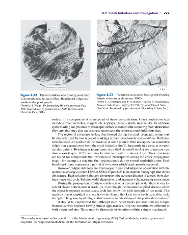
Figure 8.22 Fracture surface of a rotating steel shaft Figure 8.23 Transmission electron fractograph showing
that experienced fatigue failure. Beachmark ridges are fatigue striations in aluminum. 9000 .
visible in the photograph. (From V. J. Colangelo and F. A. Heiser, Analysis of Metallurgical
Failures, 2nd edition. Copyright © 1987 by John Wiley & Sons,
(From D. J. Wulpi, Understanding How Components Fail,
1985. Reproduced by permission of ASM International, New York. Reprinted by permission of John Wiley & Sons, Inc.)
Materials Park, OH.)
surface of a component at some point of stress concentration. Crack nucleation sites
include surface scratches, sharp fillets, keyways, threads, dents, and the like. In addition,
cyclic loading can produce microscopic surface discontinuities resulting from dislocation
slip steps that may also act as stress raisers and therefore as crack initiation sites.
The region of a fracture surface that formed during the crack propagation step may
be characterized by two types of markings termed beachmarks and striations. Both fea-
tures indicate the position of the crack tip at some point in time and appear as concentric
ridges that expand away from the crack initiation site(s), frequently in a circular or semi-
circular pattern. Beachmarks (sometimes also called clamshell marks) are of macroscopic
dimensions (Figure 8.22), and may be observed with the unaided eye. These markings
are found for components that experienced interruptions during the crack propagation
stage—for example, a machine that operated only during normal workshift hours. Each
beachmark band represents a period of time over which crack growth occurred.
However, fatigue striations are microscopic in size and subject to observation with the
electron microscope (either TEM or SEM). Figure 8.23 is an electron fractograph that shows
this feature. Each striation is thought to represent the advance distance of a crack front dur-
ing a single load cycle. Striation width depends on, and increases with, increasing stress range.
During the propagation of fatigue cracks and on a microscopic scale, there is very lo-
calized plastic deformation at crack tips, even though the maximum applied stress to which
the object is exposed in each stress cycle lies below the yield strength of the metal. This
applied stress is amplified at crack tips to the degree that local stress levels exceed the yield
strength. The geometry of fatigue striations is a manifestation of this plastic deformation. 9
It should be emphasized that although both beachmarks and striations are fatigue
fracture surface features having similar appearances, they are nevertheless different in
both origin and size. There may be thousands of striations within a single beachmark.
9 The reader is referred to Section M.10 of the Mechanical Engineering (ME) Online Module, which explains and
diagrams the proposed mechanism for the formation of fatigue striations.