
Page 148 - Materials Chemistry, Second Edition
P. 148
135
2.4. The Amorphous State
hn 0
þ
ð47Þ Cu ! Cu 2þ +Cu ðnanoparticleÞ
To synthesize photochromic glass, silica and metal halide powders are placed into a
platinum crucible and heated in air to 1,400 C, followed by pouring into slabs and
annealing at ca. 400 C overnight. Another heat treatment at a temperature around
600–650 C(ca. 1 h) is then performed to control the size of the inclusions, required
for high transmittance and spectral response. We will see examples of organic
molecules that also give rise to photochromism in Chapter 5 for plastic lenses,
CD-R memory, and molecular switch applications.
The composition of the glass is directly related to the observed photochromic
response. In general, as the silica concentration is increased, the maximum photo-
chromic response is observed as the alkali:B 2 O 3 ratio is decreased (where alkali ¼
Na 2 O:Li 2 O:K 2 O ratio). Likely, this delicate balance is related to governing the
necessary oxidation state of the metal, and size of metal halide and/or colloidal
metals precipitates formed during heat treatment. That is, metal halide solubility is
related to the number of non-bridging oxygens present in the host glass, which is
influenced by the concentrations of B and alkali metal ions, via formation of
M —O—B bonds during heating. Salts containing fluoride, tungstate or molybdate
þ
anions are also often added to alter the photochromic response. These additives
likely serve as effective nucleation agents that facilitate precipitation of metal halide
crystallites of the appropriate size during the heat treatment.
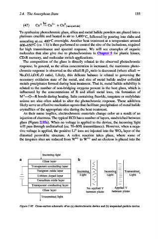
As their name implies, electrochromic materials change color as a result of an
injection of electrons. The typical ECD has a number of layers, sandwiched between
glass (Figure 2.95a). When no voltage is applied to the device, the incoming light
will pass through undisturbed (ca. 70–80% transmittance). However, when a nega-
þ
tive voltage is applied, the positive Li ions are injected into the WO 3 layer of the
distorted perovskite structure. A redox reaction takes place, where some of
the tungsten sites are reduced from W 6þ to W 5þ and an electron is placed into the
Incoming light
a b
Glass layer
Transparent conducting layer
Tungsten oxide layer Incoming Incoming Transmitted
Light Light Light
Lithium doped layer
Vanadium oxide layer
Transparent conducting layer
No applied V Applied V
Glass layer
between plates between plates
Transmitted light
Figure 2.95. Cross-section schematic of an (a) electrochromic device and (b) suspended-particle device.