
Page 47 - Materials Chemistry, Second Edition
P. 47
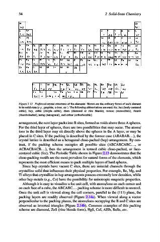
34                                              2 Solid-State Chemistry


           Figure 2.13. Preferred crystal structures of the elements. Shown are the ordinary forms of each element
           in its solid state (e.g., graphite, a-iron, etc.). The following abbreviations are used: fcc, bcc (body-centered
           cubic), hcp, cubic (simple cubic), diam (diamond or zinc blende), monoc (monoclinic), rhomb
           (rhombohedral), tetrag (tetragonal), and orthor (orthorhombic).

           arrangement, the next layer packs into B sites, formed as voids above three A spheres.
           For the third layer of spheres, there are two possibilities that may occur. The atoms/
           ions in the third layer may sit directly above the spheres in the A layer, or may be
           placed in C sites. If the packing is described by the former case (ABABAB.. .), the
           crystal lattice is described as a hexagonal close-packed (hcp) arrangement. By con-
           trast, if the packing scheme occupies all possible sites (ABCABCABC.. .,or
           ACBACBACB...), then the arrangement is termed cubic close-packed, or face-
           centered cubic (fcc). The Periodic Table shown in Figure 2.13 demonstrates that the
           close-packing motifs are the most prevalent for natural forms of the elements, which
           represents the most efficient means to pack multiple layers of hard spheres.
             Since hcp crystals have vacant C sites, there are uniaxial channels through the
           crystalline solid that influences their physical properties. For example, Be, Mg, and
           Ti alloys that crystallize in hcp arrangements possess extremely low densities, while
           other hcp metals (e.g., Co) have the possibility for anisotropic magnetic properties.
             Although it is easy to visualize a fcc unit cell, with atoms/ions on each corner and
           on each face of a cube, the ABCABC... packing scheme is more difficult to unravel.
           Once the unit cell is viewed along the cell corners, parallel to the (111) plane, the
           packing layers are readily observed (Figure 2.14a). When viewed along a vector
           perpendicular to the packing planes, the atoms/ions occupying the B and C sites are
           observed as inverted triangles (Figure 2.14b). Common examples of this packing
           scheme are diamond, ZnS (zinc blende form), HgS, CuI, AlSb, BeSe, etc.