
Page 43 - Materials Chemistry, Second Edition
P. 43
30 2 Solid-State Chemistry
(0,0,1)
(0,1,1)
c
(1,0,1) (1,1,1)
b
b
a
(0,0,0) (0,1,0)
g
a
(1,0,0) (1,1,0)
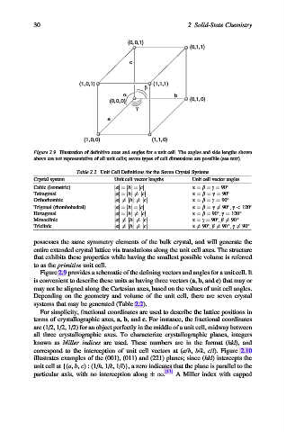
Figure 2.9. Illustration of definitive axes and angles for a unit cell. The angles and side lengths shown
above are not representative of all unit cells; seven types of cell dimensions are possible (see text).
Table 2.2. Unit Cell Definitions for the Seven Crystal Systems
Crystal system Unit cell vector lengths Unit cell vector angles
Cubic (isometric) jaj¼jbj¼jcj a ¼ b ¼ g ¼ 90
Tetragonal jaj¼jbj 6¼jcj a ¼ b ¼ g ¼ 90
Orthorhombic jaj 6¼jbj 6¼jcj a ¼ b ¼ g ¼ 90
Trigonal (rhombohedral) jaj¼jbj¼jcj a ¼ b ¼ g 6¼ 90 , g < 120
Hexagonal jaj¼jbj 6¼jcj a ¼ b ¼ 90 , g ¼ 120
Monoclinic jaj 6¼jbj 6¼jcj a ¼ g ¼ 90 , b 6¼ 90
Triclinic jaj 6¼jbj 6¼jcj a 6¼ 90 , b 6¼ 90 , g 6¼ 90
possesses the same symmetry elements of the bulk crystal, and will generate the
entire extended crystal lattice via translations along the unit cell axes. The structure
that exhibits these properties while having the smallest possible volume is referred
to as the primitive unit cell.
Figure 2.9 provides a schematic of the defining vectors and angles for a unit cell. It
is convenient to describe these units as having three vectors (a, b, and c) that may or
may not be aligned along the Cartesian axes, based on the values of unit cell angles.
Depending on the geometry and volume of the unit cell, there are seven crystal
systems that may be generated (Table 2.2).
For simplicity, fractional coordinates are used to describe the lattice positions in
terms of crystallographic axes, a, b, and c. For instance, the fractional coordinates
are (1/2, 1/2, 1/2) for an object perfectly in the middle of a unit cell, midway between
all three crystallographic axes. To characterize crystallographic planes, integers
known as Miller indices are used. These numbers are in the format (hkl), and
correspond to the interception of unit cell vectors at (a/h, b/k, c/l). Figure 2.10
illustrates examples of the (001), (011) and (221) planes; since (hkl) intercepts the
unit cell at {(a, b, c) : (1/h,1/k,1/l)}, a zero indicates that the plane is parallel to the
particular axis, with no interception along 1. [11] A Miller index with capped