
Page 121 - Mathematical Models and Algorithms for Power System Optimization
P. 121
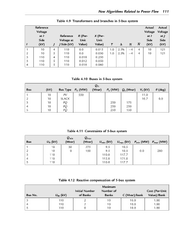
New Algorithms Related to Power Flow 111

                                  Table 4.9 Transformers and branches in 5-bus system
                     Reference                                                      Actual  Actual
                      Voltage                                                       Voltage Voltage
                        at I       Reference  R (Per-  X (Per-                       at I    at J
                       Side        Voltage at  Unit     Unit                         Side    Side
                I      (kV)     J  J Side (kV)  Value)  Value)   T    Δ    N    N    (kV)    (kV)

                1        10     4     110     0.0       0.015   1.0  2.5%   4   4     10     121
                2        10     5     110     0.0       0.030   1.0  2.5%   4   4     10     121
                3       110     4     110     0.018     0.250
                3       110     5     110     0.012     0.050
                4       110     5     110     0.018     0.060


                                          Table 4.10 Buses in 5-bus system
                                                       Q G
                Bus        (kV)    Bus Type  P G (MW)  (Mvar)  P L (MW) Q L (Mvar)  V I (kV)  θ (deg)
                                     PV
                1           10                550                                 11.0
                2           10      SLACK                                         10.7      0.0
                                     PQ
                3           10                                  250      175
                                     PQ
                4           10                                  250      250
                                     PQ
                5           10                                  250      150


                                        Table 4.11 Constraints of 5-bus system

                                       Q min      Q max
                Bus         U B (kV)  (Mvar)     (Mvar)   U min (kV)  U max (kV)  P min (MW) P max (MW)

                1             10        30        275         9.5      10.5
                2             10         0        150         9.5      10.5      0.0       280
                3            110                            110.0     117.7
                4            110                            115.0     121.0
                5            110                            110.0     117.7


                                   Table 4.12 Reactive compensation of 5-bus system
                                                            Maximum
                                            Initial Number  Number of                Cost (Per-Unit
                Bus No.          U BI (kV)    of Banks       Banks     C (Mvar)/bank  Value)/Bank

                3                  110           2             10           10.0         1.00
                4                  110           2             10           10.0         1.00
                5                  110           0             10           10.0         1.00