
Page 140 - Mathematical Models and Algorithms for Power System Optimization
P. 140
Load Optimization for Power Network 131
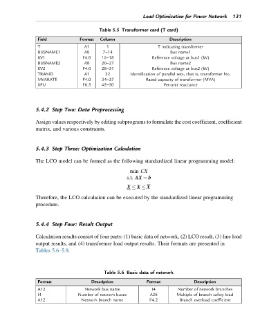
Table 5.5 Transformer card (T card)
Field Format Column Description
T A1 1 T indicating transformer
BUSNAME1 A8 7–14 Bus name1
KV1 F4.0 15–18 Reference voltage at bus1 (kV)
BUSNAME2 A8 20–27 Bus name2
KV2 F4.0 28–31 Reference voltage at bus2 (kV)
TRANID A1 32 Identification of parallel sets, that is, transformer No.
MVARATE F4.0 34–37 Rated capacity of transformer (MVA)
XPU F6.5 45–50 Per-unit reactance
5.4.2 Step Two: Data Preprocessing
Assign values respectively by editing subprograms to formulate the cost coefficient, coefficient
matrix, and various constraints.
5.4.3 Step Three: Optimization Calculation
The LCO model can be formed as the following standardized linear programming model:
min CX
s.t. AX ¼ b
X X X
Therefore, the LCO calculation can be executed by the standardized linear programming
procedure.
5.4.4 Step Four: Result Output
Calculation results consist of four parts: (1) basic data of network, (2) LCO result, (3) line load
output results, and (4) transformer load output results. Their formats are presented in
Tables 5.6–5.9.
Table 5.6 Basic data of network
Format Description Format Description
A12 Network bus name I4 Number of network branches
I4 Number of network buses A26 Multiple of branch safety load
A12 Network branch name F4.2 Branch overload coefficient