
Page 249 - Mathematical Models and Algorithms for Power System Optimization
P. 249
Optimization Method for Load Frequency Feed Forward Control 241
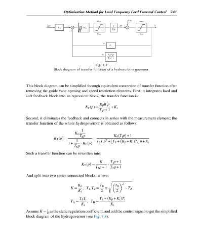
Fig. 7.7
Block diagram of transfer function of a hydroturbine governor.
This block diagram can be simplified through equivalent conversion of transfer function after
removing the guide vane opening and speed restriction elements. First, it integrates hard and
soft feedback block into an equivalent block; the transfer function is:
K β K i p
K F pðÞ ¼ + K i
T i p +1
Second, it eliminates the feedback and connects in series with the measurement element; the
transfer function of the whole hydrogovernor is obtained as follows:
1
K δ
T S p K δ T i pÞ +1
ð
K T pðÞ ¼ ¼
1 2
1+ K F pðÞ T S T i p + T S + K β + K i T i p + K i
T S p
Such a transfer function can be rewritten into:
K T i p +1
K T pðÞ ¼
T 1 p +1 T 2 p +1
And split into two series-connected blocks, where:
s ffiffiffiffiffiffiffiffiffiffiffiffiffiffiffiffiffiffiffiffiffiffiffiffiffi
2
K δ T B T B
K ¼ , T 1 ,T 2 ¼ T A
K i 2 2
T S T i T S + K β + K i T i
T A ¼ , T B ¼
K i K i
1
Assume K ¼ as the static regulation coefficient, and add the control signal to get the simplified
R
block diagram of the hydrogovernor (see Fig. 7.8).