
Page 251 - Mathematical Models and Algorithms for Power System Optimization
P. 251
Optimization Method for Load Frequency Feed Forward Control 243
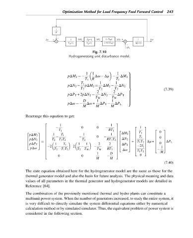
Fig. 7.10
Hydrogenerating unit disturbance model.
9
1 1 1
pΔM 2 ¼ Δω Δμ >
>
T 1 R T 1 ΔM 2>
>
>
>
T i 1 1 >
>
>
pΔN 2 pΔM 2 ¼ ΔM 2 ΔN 2 =
T 2 T 2 T 2 (7.39)
2 2 >
pΔP T +2pΔN 2 ¼ ΔN 2 ΔP T >
>
>
T W T W >
>
D 1 1 >
>
pΔω ¼ Δω + ΔP T ΔP L >
;
M M M
Rearrange this equation to get:
1 1
2 3
0 0 2 1 3
T 1
6 7 2 3
2 3
RT 1 7
6 0
2 3 7 ΔM 2 6 T 1 7
6 1 1 1
pΔM 2 T i 6 7
0 6 7 6 T i 7
6 7 6 7
6 7 6 0 7
pΔN 2 T 2 T 1 T 2 T 2
6 7 6 ΔN 2 7 6 7
6 RT 1 T 2 7 6 7
6 7 6 7 6 7 7ΔP L
¼ 6 7 + T 1 T 2 7 Δμ + 6
4 5 1 1 1 2 2 6 7 6
pΔP T 6 T i 7 ΔP T 5 6 7 6 0 7
4
pΔω 6 2 2 7 6 2T i 7 4 1 5
7
6
6 T 2 T 1 T 2 T 2 T W T W RT 2 7 Δω 4 T 1 T 2 5 M
1 D
4 5
0 0 0
M M
(7.40)
The state equation obtained here for the hydrogenerator model are the same as those for the
thermal generator model and also the basis for future analysis. The physical meaning and data
values of all parameters in the thermal generator and hydrogenerator models are detailed in
Reference [84].
The combination of the previously mentioned thermal and hydro plants can constitute a
multiunit power system. When the number of generators increased, to study the entire system, it
is very difficult to directly simulate the system differential equations either by numerical
calculation method or by simulated simulator. Thus, the equivalent problem of power system is
considered in the following section.