
Page 248 - Mathematical Models and Algorithms for Power System Optimization
P. 248
240 Chapter 7
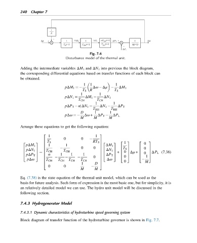
Fig. 7.6
Disturbance model of the thermal unit.
Adding the intermediate variables ΔM 1 and ΔN 1 into previous the block diagram,
the corresponding differential equations based on transfer functions of each block can
be obtained.
1 1 1
pΔM 1 ¼ Δω Δμ ΔM 1
T S R T S
1 1
pΔN 1 ¼ ΔM 1 ΔN 1
T CH T CH
1 1
pΔP T αjΔN 1 ¼ ΔN 1 ΔP T
T RH T RH
D 1 1
pΔω ¼ Δω + ΔP T ΔP L
M M M
Arrange these equations to get the following equation:
2 3
1 1
0 0
T S
6 7 2 3 2 3
2 3 RT S 2 3 1 0
6 7
pΔM 1 1 1 7 ΔM 1
6
0 0
6 7 6 T S 7 6 0 7
pΔN 1 7 ΔN 1
6 7 6 7
6 T CH T CH 6 7 6 7
6 7 6 7 0 7Δμ + 6 0 7ΔP L (7.38)
pΔP T 7 ΔP T
4 5 ¼ 6 α 1 1 1 7 4 5 + 6
6 0 4 0 5 4 1 5
pΔω 6 7 Δω
6 T CH T CH T CH T CH 7 0 M
1 D
4 5
0 0
M M
Eq. (7.38) is the state equation of the thermal unit model, which can be used as the
basis for future analysis. Such form of expression is the most basic one, but for simplicity, it is
an relatively detailed model we can use. The hydro unit model will be discussed in the
following section.
7.4.3 Hydrogenerator Model
7.4.3.1 Dynamic characteristics of hydroturbine speed governing system
Block diagram of transfer function of the hydroturbine governor is shown in Fig. 7.7.