
Page 246 - Mathematical Models and Algorithms for Power System Optimization
P. 246
238 Chapter 7
1
Δω ¼ ð Δp T Δp L Þ (7.37)
Mp + D
d
where p ¼ is the differential operator.
dt
Its block diagram is shown in Fig. 7.1.
Fig. 7.1
Generator model.
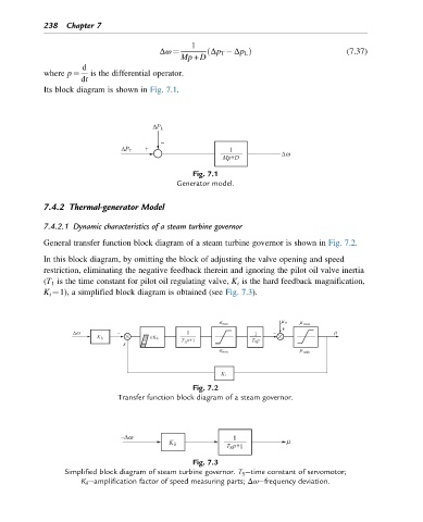
7.4.2 Thermal-generator Model
7.4.2.1 Dynamic characteristics of a steam turbine governor
General transfer function block diagram of a steam turbine governor is shown in Fig. 7.2.
In this block diagram, by omitting the block of adjusting the valve opening and speed
restriction, eliminating the negative feedback therein and ignoring the pilot oil valve inertia
(T 1 is the time constant for pilot oil regulating valve, K i is the hard feedback magnification,
K i ¼1), a simplified block diagram is obtained (see Fig. 7.3).
Fig. 7.2
Transfer function block diagram of a steam governor.
Fig. 7.3
Simplified block diagram of steam turbine governor. T S —time constant of servomotor;
K δ —amplification factor of speed measuring parts; Δω—frequency deviation.