
Page 247 - Mathematical Models and Algorithms for Power System Optimization
P. 247
Optimization Method for Load Frequency Feed Forward Control 239
7.4.2.2 Dynamic characteristics of a steam turbine
The effect of steam volume is reflected in the inertia of steam in the pipelines and reheaters
during the transient process of the steam turbine. When the steam turbine adjusts the steam
valve opening due to the existence of certain steam volume between the steam valve and nozzle,
the steam pressure cannot be changed immediately, so the power input goes into turbine, and
there is a time lag. The effects of steam volume can be mathematically simulated by first-order
inertial model, with transfer function expressed as follows:
1
ΔP T ¼ μ
T CH p +1
where T CH —time constant of steam volume; μ—steam valve opening.
For an intermediate reheat steam turbine, the intermediate reheat system has a larger steam volume,
and the change in the output power of the medium/low-pressure cylinder will be affected by this
portion of the steam inertia, which can also be expressed by a first-order inertia model. For the
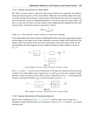
general turbine, the block diagram of steam volume simulation of reheat turbines is shown in
Fig. 7.4.
Fig. 7.4
Block diagram of steam volume simulation of reheat turbine.
In Fig. 7.4, α and 1 α are the ratio of total power of the high (and medium and low) pressure
cylinder to the total turbine power, respectively. T CH and T RH are the time constants of high-
pressure cylinder and reheat system steam volume, respectively. In Fig. 7.4, the proportional
element α and inertial element 1 α are put in parallel to get Fig. 7.5.
T CH p +1
Fig. 7.5
Block diagram of dynamic characteristics for a steam turbine.
7.4.2.3 Dynamic characteristics of thermal generating unit
Based on the combination of Figs. 7.1, 7.3 and 7.5, with the input control signal Δu,a
1
disturbance model of thermal unit can be obtained, as shown in Fig. 7.6 (where R ¼ is speed
K δ
adjusting rate).