
Page 131 - Mechanical design of microresonators _ modeling and applications
P. 131
0-07-145538-8_CH03_130_08/30/05
Microhinges and Microcantilevers: Lumped-Parameter Modeling and Design
130 Chapter Three
60
0.1
rω
0
0.1
0.1
cw
cr
0.01
1
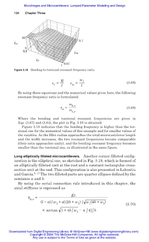
Figure 3.18 Bending-to-torsional resonant frequency ratio.
R w 1
c = l c = l (3.68)
w
r
By using these equations and the numerical values given here, the following
resonant frequency ratio is formulated:
Ȧ
r = b,e (3.69)
Ȧ
Ȧ
t,e
Where the bending and torsional resonant frequencies are given in
Eqs. (3.67) and (3.64), the plot in Fig. 3.18 is obtained.
Figure 3.18 indicates that the bending frequency is higher than the tor-
sional one for the numerical values of this example and for smaller values of
the vaiables. As the fillet radius approaches the total microcantilever length
and the width increases, the two resonant frequencies become comparable
(their ratio approaches unity), and the bending resonant frequency becomes
smaller than the torsional one, as illustrated in the same figure.
Long elliptically filleted microcantilevers. Another corner-filleted config-
uration is the elliptical one, as sketched in Fig. 3.19, which is formed of
an elliptically filleted unit at the root and a constant rectangular cross-
section unit at the end. This configuration is also presented in Lobontiu
and Garcia. 5, 17 The two filleted parts are quarter ellipses defined by the
semiaxes a and b.
By using the serial connection rule introduced in this chapter, the
axial stiffness is expressed as
Et
k a,e =
(l í a) w + a (2b + w ) w (4b + w ) (3.70)
1 /
/
1
1
1
/ /
/
×arctan 1+ 4b w íʌ 4 b
1
Downloaded from Digital Engineering Library @ McGraw-Hill (www.digitalengineeringlibrary.com)
Copyright © 2004 The McGraw-Hill Companies. All rights reserved.
Any use is subject to the Terms of Use as given at the website.