
Page 128 - Mechanical design of microresonators _ modeling and applications
P. 128
0-07-145538-8_CH03_127_08/30/05
Microhinges and Microcantilevers: Lumped-Parameter Modeling and Design
Microhinges and Microcantilevers: Lumped-Parameter Modeling and Design 127
y
fixed
R
w
w1
x
x
R
1
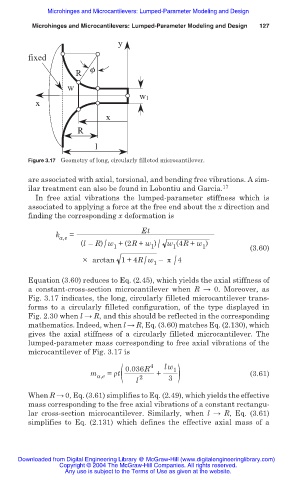
Figure 3.17 Geometry of long, circularly filleted microcantilever.
are associated with axial, torsional, and bending free vibrations. A sim-
ilar treatment can also be found in Lobontiu and Garcia. 17
In free axial vibrations the lumped-parameter stiffness which is
associated to applying a force at the free end about the x direction and
finding the corresponding x deformation is
Et
k a,e =
1 /
(l – R) w + (2R + w ) w (4R + w ) (3.60)
/
1
1
1
/
/
× arctan 1+ 4R w – ʌ 4
1
Equation (3.60) reduces to Eq. (2.45), which yields the axial stiffness of
a constant-cross-section microcantilever when R ĺ 0. Moreover, as
Fig. 3.17 indicates, the long, circularly filleted microcantilever trans-
forms to a circularly filleted configuration, of the type displayed in
Fig. 2.30 when l ĺ R, and this should be reflected in the corresponding
mathematics. Indeed, when l ĺ R, Eq. (3.60) matches Eq. (2.130), which
gives the axial stiffness of a circularly filleted microcantilever. The
lumped-parameter mass corresponding to free axial vibrations of the
microcantilever of Fig. 3.17 is
a,e ( 0.036R 4 lw 1
m = ȡt + 3 ) (3.61)
l 2
When R ĺ 0, Eq. (3.61) simplifies to Eq. (2.49), which yields the effective
mass corresponding to the free axial vibrations of a constant rectangu-
lar cross-section microcantilever. Similarly, when l ĺ R, Eq. (3.61)
simplifies to Eq. (2.131) which defines the effective axial mass of a
Downloaded from Digital Engineering Library @ McGraw-Hill (www.digitalengineeringlibrary.com)
Copyright © 2004 The McGraw-Hill Companies. All rights reserved.
Any use is subject to the Terms of Use as given at the website.