Page 124 - Mechanical design of microresonators _ modeling and applications
P. 124

0-07-145538-8_CH03_123_08/30/05


                                   Microhinges and Microcantilevers: Lumped-Parameter Modeling and Design

                               Microhinges and Microcantilevers: Lumped-Parameter Modeling and Design  123


                                  6
                                                                   2
                              rkb
                                   0
                                  0.1
                                                                c1
                                           cw
                                                          0.2
                                                       0.9
                              Figure 3.13 Bending stiffness comparison between the microcantilever of Fig. 3.11 and
                              the reversed configuration of Fig. 3.12.


                              UPE


                                                               F
                                           FZ


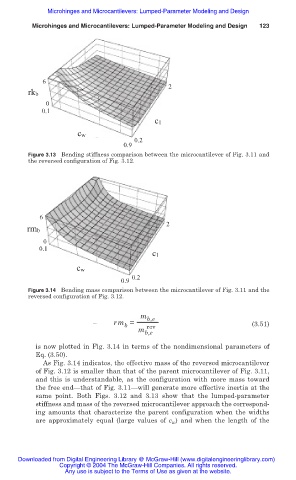
                              Figure 3.14 Bending mass comparison between the microcantilever of Fig. 3.11 and the
                              reversed configuration of Fig. 3.12.

                                                            m b,e
                                                     rm =                                 (3.51)
                                                        b
                                                           m  rev
                                                             b,e
                                is now plotted in Fig. 3.14 in terms of the nondimensional parameters of
                                Eq. (3.50).
                                  As Fig. 3.14 indicates, the effective mass of the reversed microcantilever
                                of Fig. 3.12 is smaller than that of the parent microcantilever of Fig. 3.11,
                                and this is understandable,  as the configuration  with  more  mass toward
                                the free end—that of Fig. 3.11—will generate more effective inertia at the
                                same  point. Both Figs.  3.12  and 3.13 show  that the lumped-parameter
                                stiffness and mass of the reversed microcantilever approach the correspond-
                                ing  amounts that characterize the parent  configuration when the widths
                                are  approximately equal (large values of  c w )  and  when the length of the


                           Downloaded from Digital Engineering Library @ McGraw-Hill (www.digitalengineeringlibrary.com)
                                      Copyright © 2004 The McGraw-Hill Companies. All rights reserved.
                                        Any use is subject to the Terms of Use as given at the website.
   119   120   121   122   123   124   125   126   127   128   129