
Page 120 - Mechanical design of microresonators _ modeling and applications
P. 120
0-07-145538-8_CH03_119_08/30/05
Microhinges and Microcantilevers: Lumped-Parameter Modeling and Design
Microhinges and Microcantilevers: Lumped-Parameter Modeling and Design 119
3 3
Et t w
1 2
k b,e = (3.39)
3 3
2 3
2
4 l (3l +3l l + l )t + l t
2 1 1 2 2 1 1 2
The effective bending mass is
3
3
4
2 2
ȡw{ l t (33l +231l l + 693l l + 1155l l 3
1 2
1 2
1
1 2
1 1
4
5
2
+1155l ) + l 33l t +7l l (20t +13t )
2
1
2
2 2
2
1 2
(3.40)
2
+63l (10t + t ) }
1
1
2
m b,e =
140(l + l ) 6
2
1
The bending resonant frequency is
Et t
1 2
5.92t t (l + l ) 3
1 2 1 2 2 2 3 3 3
ȡ [ l (3l +3l l + l )t + l t ]
1 2
2 1
1
1 2
2
Ȧ b,e =
3
3
2 2
4
4
3
l t (33l + 231l l + 693l l +1155l l + 1155l ) (3.41)
1 2
1 2
1
2
1 1
1 2
5
2
2
+l 33l t +7l l (20t +13t ) +63l (10t + t )
1
2 2
2
2
1
1
2
1 2
All the lumped-parameter stiffness and inertia parameters corre-
sponding to this microcantilever simplify to those of a constant
rectangular cross-section design of length l, width w, and thickness t
when l 1 = l 2 = l/2 and t 1 = t 2 .
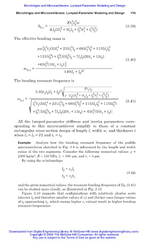
Example: Analyze how the bending resonant frequency of the paddle
microcantilever sketched in Fig. 3.9 is influenced by the length and width
ratios of the two segments. Consider the following numerical values: ȡ =
3
2300 kg/m , E = 150 GPa, l 1 = 500 m, and t 1 = 3 m.
By using the relationships
l = c l
2 l 1
(3.42)
t = c t
2 t 1
and the given numerical values, the resonant bending frequency of Eq. (3.41)
can be studied more closely, as illustrated in Fig. 3.10.
Figure 3.10 suggests that configurations with relatively shorter roots
(shorter l 2 and therefore smaller values of c l ) and thicker ones (larger values
of t 2 approaching t 1 , which means higher c t values) result in higher bending
resonant frequencies.
Downloaded from Digital Engineering Library @ McGraw-Hill (www.digitalengineeringlibrary.com)
Copyright © 2004 The McGraw-Hill Companies. All rights reserved.
Any use is subject to the Terms of Use as given at the website.