
Page 117 - Mechanical design of microresonators _ modeling and applications
P. 117
0-07-145538-8_CH03_116_08/30/05
Microhinges and Microcantilevers: Lumped-Parameter Modeling and Design
116 Chapter Three
y
w2
w1
x
1 2 1 1
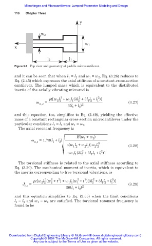
Figure 3.8 Top view and geometry of paddle microcantilever.
and it can be seen that when l = l and w = w , Eq. (3.26) reduces to
2
2
1
1
Eq. (2.45) which expresses the axial stiffness of a constant-cross-section
cantilever. The lumped mass which is equivalent to the distributed
inertia of the axially vibrating microrod is
2
2
3
ȡt w l + w l (3l +3l l + l )
m a,e = 2 2 1 1 2 1 2 1 (3.27)
3(l + l ) 2
1 2
and this equation, too, simplifies to Eq. (2.49), yielding the effective
mass of a constant rectangular cross-section microcantilever under the
particular conditions l 1 = l 2 and w 1 = w 2 .
The axial resonant frequency is
E(w + w )
1
2
Ȧ =1.73(l + l )
a,e 1 2 3
ȡ(w l + w l ) w l (3.28)
1 2
2 2
2 1
2
2
+w l (3l +3l l + l )
1 1 2 1 2 1
The torsional stiffness is related to the axial stiffness according to
Eq. (3.20). The mechanical moment of inertia, which is equivalent to
the inertia corresponding to free torsional vibrations, is
2
2
2
2
2
2
3
ȡt w l (w + t ) + w l (w + t )(3l +3l l + l )
2 2
1 2
2
1
1 1
1
2
J = (3.29)
t,e 2
36(l + l )
2
1
and this equation simplifies to Eq. (2.55) when the limit conditions
l 1 = l 2 and w 1 = w 2 are satisfied. The torsional resonant frequency is
found to be
Downloaded from Digital Engineering Library @ McGraw-Hill (www.digitalengineeringlibrary.com)
Copyright © 2004 The McGraw-Hill Companies. All rights reserved.
Any use is subject to the Terms of Use as given at the website.