
Page 112 - Mechanical design of microresonators _ modeling and applications
P. 112
0-07-145538-8_CH03_111_08/30/05
Microhinges and Microcantilevers: Lumped-Parameter Modeling and Design
Microhinges and Microcantilevers: Lumped-Parameter Modeling and Design 111
y y1
1
x1 O
w
O1
x
x a
x1
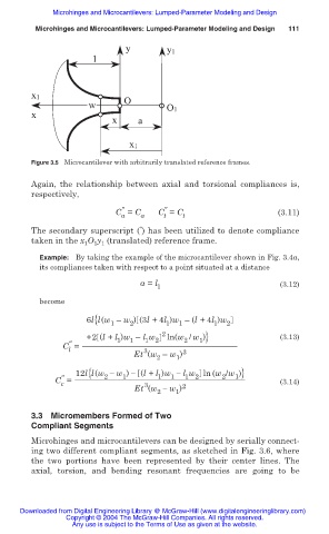
Figure 3.5 Microcantilever with arbitrarily translated reference frames.
Again, the relationship between axial and torsional compliances is,
respectively,
ҡ ҡ
C = C a C = C t (3.11)
a
t
Ǝ
The secondary superscript ( ) has been utilized to denote compliance
taken in the x O y (translated) reference frame.
1 1
1
Example: By taking the example of the microcantilever shown in Fig. 3.4a,
its compliances taken with respect to a point situated at a distance
a = l (3.12)
1
become
6l{l(w – w ) (3l +4l )w – (l +4l )w
1 2 1 1 1 2
+2 (l + l )w – l w 2 ln(w / w )} (3.13)
ҡ 1 1 1 2 2 1
C =
l
3
Et (w – w ) 3
2 1
12l{l(w í w ) í (l + l )w í l w ln (w /w )}
ҡ 2 1 1 1 1 2 2 1
C = (3.14)
c
3
Et (w í w ) 2
2 1
3.3 Micromembers Formed of Two
Compliant Segments
Microhinges and microcantilevers can be designed by serially connect-
ing two different compliant segments, as sketched in Fig. 3.6, where
the two portions have been represented by their center lines. The
axial, torsion, and bending resonant frequencies are going to be
Downloaded from Digital Engineering Library @ McGraw-Hill (www.digitalengineeringlibrary.com)
Copyright © 2004 The McGraw-Hill Companies. All rights reserved.
Any use is subject to the Terms of Use as given at the website.