
Page 109 - Mechanical design of microresonators _ modeling and applications
P. 109
0-07-145538-8_CH03_108_08/30/05
Microhinges and Microcantilevers: Lumped-Parameter Modeling and Design
108 Chapter Three
y1 y
O
x O1 w x1
x1 x
l
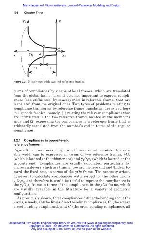
Figure 3.3 Microhinge with two end reference frames.
terms of compliances by means of local frames, which are translated
from the global frame. Thus it becomes important to express compli-
ances (and stiffnesses, by consequence) in reference frames that are
translated from the original ones. Two types of problems relating to
compliance transforms by reference frame translation are solved here
in a generic fashion, namely, (1) relating the relevant compliances that
are formulated in the two reference frames located at the member’s
ends and (2) expressing the compliances in a reference frame that is
arbitrarily translated from the member’s end in terms of the regular
compliances.
3.2.1 Compliances in opposite-end
reference frames
Figure 3.3 shows a microhinge, which has a variable width. This vari-
able width can be expressed in terms of two reference frames, yOx
(which is located at the thinner end) and y 1 O 1 x 1 (which is located at the
opposite end). Compliances are usually calculated, particularly for
microcantilevers which are thinner toward the free end and thicker to-
ward the fixed root, in terms of the yOx frame. The necessity arises,
however, to calculate compliances with respect to the other frame
y 1 O 1 x 1 , and therefore it would be useful to express the compliances in
the y 1 O 1 x 1 frame in terms of the compliances in the yOx frame, which
are usually available in the literature for a variety of geometric
configurations.
As previously shown, three compliances define the bending about the
y axis, namely, C l (the linear direct bending compliance), C r (the rotary
direct bending compliance), and C c (the cross-bending compliance), all
Downloaded from Digital Engineering Library @ McGraw-Hill (www.digitalengineeringlibrary.com)
Copyright © 2004 The McGraw-Hill Companies. All rights reserved.
Any use is subject to the Terms of Use as given at the website.