
Page 110 - Mechanical design of microresonators _ modeling and applications
P. 110
0-07-145538-8_CH03_109_08/30/05
Microhinges and Microcantilevers: Lumped-Parameter Modeling and Design
Microhinges and Microcantilevers: Lumped-Parameter Modeling and Design 109
α
w w1 w
x
x
1
(a) (b)
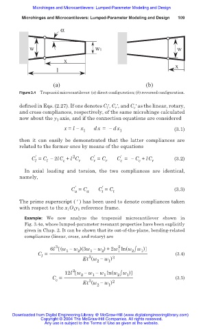
Figure 3.4 Trapezoid microcantilever: (a) direct configuration; (b) reversed configuration.
defined in Eqs. (2.27). If one denotes C ƍ, C ƍ, and C ƍ as the linear, rotary,
c
r
l
and cross compliances, respectively, of the same microhinge calculated
now about the y 1 axis, and if the connection equations are considered
x = l í x dx = í dx (3.1)
1 1
then it can easily be demonstrated that the latter compliances are
related to the former ones by means of the equations
2
Ҡ
Ҡ
Ҡ
C = C í 2lC + l C C = C C = í C + lC (3.2)
l l c r r r c c r
In axial loading and torsion, the two compliances are identical,
namely,
Ҡ Ҡ
C = C a C = C t (3.3)
t
a
The prime superscript ( ƍ ) has been used to denote compliances taken
with respect to the x 1 O 1 y 1 reference frame.
Example: We now analyze the trapezoid microcantilever shown in
Fig. 3.4a, whose lumped-parameter resonant properties have been explicitly
given in Chap. 2. It can be shown that its out-of-the-plane, bending-related
compliances (linear, cross, and rotary) are
3 2
w )
6l (w í w )(3w í w ) +2w ln(w 2/ 1
1
1
2
1
2
C = (3.4)
l
3
Et (w í w ) 3
2
1
2
w )
12l w í w í w ln(w 2/ 1
1
2
1
C = (3.5)
c
3
Et (w í w ) 2
2 1
Downloaded from Digital Engineering Library @ McGraw-Hill (www.digitalengineeringlibrary.com)
Copyright © 2004 The McGraw-Hill Companies. All rights reserved.
Any use is subject to the Terms of Use as given at the website.