
Page 113 - Mechanical design of microresonators _ modeling and applications
P. 113
0-07-145538-8_CH03_112_08/30/05
Microhinges and Microcantilevers: Lumped-Parameter Modeling and Design
112 Chapter Three
z
3 2 1
x
1 2 1 1
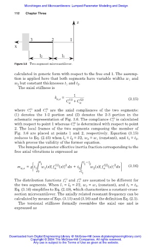
Figure 3.6 Two-segment microcantilever.
calculated in generic form with respect to the free end 1. The assump-
tion is applied here that both segments have variable widths w and
1
w but constant thicknesses t and t .
2
2
1
The axial stiffness is
1
k =
a,e (1) (2) (3.15)
C a + C a
(1)
(2)
where C a and C a are the axial compliances of the two segments:
(1) denotes the 1-2 portion and (2) denotes the 2-3 portion in the
(1)
schematic representation of Fig. 3.6. The compliance C a is calculated
(2)
with respect to point 1 whereas C a is determined with respect to point
2. The local frames of the two segments composing the member of
Fig. 3.6 are placed at points 1 and 2, respectively. Equation (3.15)
reduces to Eq. (2.45) when l = l = l/2, w = w (constant), and t = t ,
1
1
2
2
1
2
which proves the validity of the former equation.
The lumped-parameter effective inertia fraction corresponding to the
free axial vibrations is expressed as
l 1 l + l 2
1
2
m a,e = ȡ t 1ฒ w (x) f a (1) (x) 2 dx + t 2ฒ w (x) f a (2) (x) dx (3.16)
2
1
0 l
1
(2)
(1)
The distribution functions f a and f a are assumed to be different for
the two segments. When l 1 = l 2 = l/2, w 2 = w 1 (constant), and t 1 = t 2 ,
Eq. (3.16) simplifies to Eq. (2.49), which characterizes a constant-cross-
section microcantilever. The axially related resonant frequency can be
calculated by means of Eqs. (3.15) and (3.16) and the definition Eq. (2.1).
The torsional stiffness formally resembles the axial one and is
expressed as
Downloaded from Digital Engineering Library @ McGraw-Hill (www.digitalengineeringlibrary.com)
Copyright © 2004 The McGraw-Hill Companies. All rights reserved.
Any use is subject to the Terms of Use as given at the website.