
Page 116 - Mechanical design of microresonators _ modeling and applications
P. 116
0-07-145538-8_CH03_115_08/30/05
Microhinges and Microcantilevers: Lumped-Parameter Modeling and Design
Microhinges and Microcantilevers: Lumped-Parameter Modeling and Design 115
y
symmetry axis
2
x 3
l
second mirrored segment l/2 first segment
l
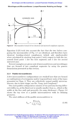
Figure 3.7 Micromember formed of two identical and mirrored compliant segments.
Equation (3.25) took into account the fact that the two halves com-
posing the micromember of Fig. 3.7 are identical, and therefore have
identical bending-related compliances (which add algebraically)
when calculated by starting from point 2 with respect to both the (as-
sumed) fixed point 1 (for the first segment) and 3 (for the second
mirrored one).
Several examples are given next of microcantilevers and microhinges
that are formed of two compliant segments by using the generic
formulation presented in this section.
3.3.1 Paddle microcantilevers
A few microcantilever configurations are studied here that are formed
as combinations of rectangular and/or trapezoid basic units of the types
presented in Chap. 2. They are collectively named paddle microcan-
tilevers, due to their shape; see Ilic, Yang, and Craighead. 9
One such paddle configuration consists of two portions having differ-
ent widths (w 2 at the fixed root is usually smaller than w 1 , which is the
width at the free end) and generally the same thickness t. Figure 3.8
shows the top view of a paddle microcantilever with its defining
geometry.
The axial stiffness of the paddle microcantilever is
Etw w
1 2
k = (3.26)
a,e w l + w l
2 1
1 2
Downloaded from Digital Engineering Library @ McGraw-Hill (www.digitalengineeringlibrary.com)
Copyright © 2004 The McGraw-Hill Companies. All rights reserved.
Any use is subject to the Terms of Use as given at the website.