
Page 118 - Mechanical design of microresonators _ modeling and applications
P. 118
0-07-145538-8_CH03_117_08/30/05
Microhinges and Microcantilevers: Lumped-Parameter Modeling and Design
Microhinges and Microcantilevers: Lumped-Parameter Modeling and Design 117
w w G
1 2
w t,e =3.464(l + l )t
2
1
2
3
2
ȡ(w l + w l ) w l (w + t ) (3.30)
1 2
2 1
2 2
2
2
2
2
2
+w l (w + t )(3l +3l l + l )
2
1 2
1
1 1
1
The bending stiffness is
3
Et w w
1 2
k b,e = (3.31)
3
2
2
4 w l + w l (3l +3l l + l )
2 1 1 2 1 1 2 2
and when l 1 = l 2 and w 1 = w 2 , it reduces to Eq. (2.61), which defines the
linear direct bending stiffness of a constant rectangular cross-section
microcantilever.
The lumped mass which is located at the free tip and is dynamically
equivalent to the distributed inertia of the bending vibrating
microcantilever is
4
3
3
2 2
ȡt w l (33l +231l l +693l l
1 1 1 1 2 1 2
3
2 5
4
+1155l l + 1155l ) +63(10w + w )l l
1 2 2 1 2 1 2
(3.32)
6
+7(20w +13w )l l +33w l 7
2 1 2
2 2
1
m b,e =
140(l + l ) 6
2
1
For l = l and w = w , the mass fraction of Eq. (3.32) simplifies to
1
2
1
2
Eq. (2.66), which gives the bending-related effective mass of a constant
rectangular cross-section microcantilever. The bending-related reso-
nant frequency is
3
ȡ w l + w l
/
1 2
2 1
3
5.92(l + l ) t Ew w { × (3l +3l l + l ) }
1 2 1 2 2 2
w = 1 1 2 2 (3.33)
b,e
2 2
3
4
4
3
3
w l (33l +231l l + 693l l +1155l l + 1155l )
1 1 1 1 2 1 2 1 2 2
6
2 5
+63(10w + w )l l +7(20w +13w )l l +33w l 7
1 2 1 2 1 2 1 2 2 2
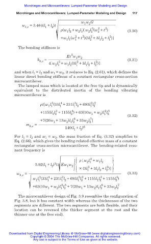
The microcantilever design of Fig. 3.9 resembles the configuration of
Fig. 3.8, but it has constant width whereas the thicknesses of the two
segments are different. The two segments are both flexible, and their
location can be reversed (the thicker segment at the root and the
thinner one at the free end).
Downloaded from Digital Engineering Library @ McGraw-Hill (www.digitalengineeringlibrary.com)
Copyright © 2004 The McGraw-Hill Companies. All rights reserved.
Any use is subject to the Terms of Use as given at the website.