
Page 123 - Mechanical design of microresonators _ modeling and applications
P. 123
0-07-145538-8_CH03_122_08/30/05
Microhinges and Microcantilevers: Lumped-Parameter Modeling and Design
122 Chapter Three
y
w1
w2
x
1 1 1 2
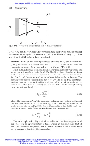
Figure 3.12 Top view of reversed trapezoid-root microcantilever.
l 1 = l 2 = l/2 and w 1 = w 2 and the corresponding properties characterizing
a constant rectangular cross-section microcantilever of length l, thick-
ness t, and width w have been obtained.
Example: Compare the bending stiffness, effective mass, and resonant fre-
quency of the microcantilever sketched in Fig. 3.11 to the similar lumped-
parameter amounts of the reversed microcantilever of Fig. 3.12.
The bending stiffness of this microcantilever is calculated by applying the
series connection rule given in Eq. (3.22). The direct linear bending stiffness
of the constant-cross-section segment located at the free end is given in
Eq. (2.61), and the corresponding compliance is its algebraic inverse. The
bending compliances (direct linear, direct rotary, and cross) of the root trape-
zoid segment are expressed in Eqs. (3.4) through (3.6), where w 2 has to be
used instead of w 1 (and vice versa), and l 1 instead of l. The following bending
ratio can be formulated:
rev
k b,e
rk = (3.49)
b k b,e
where the superscript “rev” (for reversed) indicates the bending stiffness of
the microcantilever of Fig. 3.12 and k b,e is the bending stiffness of the
configuration shown in Fig. 3.11. The stiffness ratio of Eq. (3.49) can be ex-
pressed in terms of the following nondimensional parameters:
w 2 l 2
c = c = (3.50)
w w l l
1 1
This ratio is plotted in Fig. 3.13 which indicates that the configuration of
Fig. 3.12 can be approximately 6 times stiffer in bending than that of
Fig. 3.11. A similar comparison can be made in terms of the effective mass
corresponding to bending. The mass ratio
Downloaded from Digital Engineering Library @ McGraw-Hill (www.digitalengineeringlibrary.com)
Copyright © 2004 The McGraw-Hill Companies. All rights reserved.
Any use is subject to the Terms of Use as given at the website.