Page 125 - Mechanical design of microresonators _ modeling and applications
P. 125

0-07-145538-8_CH03_124_08/30/05


                                   Microhinges and Microcantilevers: Lumped-Parameter Modeling and Design

                              124   Chapter Three


                                  6
                                                                    2
                              rωb
                                   0
                                  0.1
                                                                c1
                                            cw
                                                           0.2
                                                        0.9
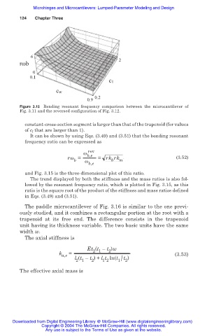
                              Figure 3.15 Bending resonant frequency  comparison between the microcantilever of
                              Fig. 3.11 and the reversed configuration of Fig. 3.12.

                                constant-cross-section segment is larger than that of the trapezoid (for values
                                of c l  that are larger than 1).
                                  It can be shown by using Eqs. (3.49) and (3.51) that the bending resonant
                                frequency ratio can be expressed as

                                                        rev
                                                      Ȧ b,e
                                                rȦ =        = rk rk m                     (3.52)
                                                   b
                                                                 b
                                                       Ȧ
                                                        b,e
                                and Fig. 3.15 is the three-dimensional plot of this ratio.
                                  The trend displayed by both the stiffness and the mass ratios is also fol-
                                lowed by the resonant frequency ratio, which is plotted in Fig. 3.15, as this
                                ratio is the square root of the product of the stiffness and mass ratios defined
                                in Eqs. (3.49) and (3.51).
                                The paddle microcantilever of Fig. 3.16 is similar to the one previ-
                              ously studied, and it combines a rectangular portion at the root with a
                              trapezoid at its free  end. The  difference  consists in the trapezoid
                              unit having its thickness variable. The two basic units have the same
                              width w.
                                The axial stiffness is

                                                        Et (t – t )w
                                                          2 1
                                                                2
                                             k a,e  =                                    (3.53)
                                                   l (t – t ) + l t ln(t 1/ 2
                                                                      t )
                                                              1 2
                                                         2
                                                   2 1
                              The effective axial mass is


                           Downloaded from Digital Engineering Library @ McGraw-Hill (www.digitalengineeringlibrary.com)
                                      Copyright © 2004 The McGraw-Hill Companies. All rights reserved.
                                        Any use is subject to the Terms of Use as given at the website.
   120   121   122   123   124   125   126   127   128   129   130