
Page 135 - Mechanical design of microresonators _ modeling and applications
P. 135
0-07-145538-8_CH03_134_08/30/05
Microhinges and Microcantilevers: Lumped-Parameter Modeling and Design
134 Chapter Three
inertia in this trend. It can also be seen that for relatively small values of a
(the “length” of the fillet) the increase in resonant frequency is somewhat
limited, irrespective of the increase in b; conversely, this is also valid for rel-
atively small values of b.
3.3.3 Filleted microhinges
By combining again filleted units (either circular or elliptical) and con-
stant rectangular cross-section units, compound members can be ob-
tained, which have a center of symmetry and which can be utilized as
flexible connectors, called microhinges. The microhinges are generally
active through bending and/or torsion, and therefore these two vibra-
tional modes together with the axial one are analyzed. Three configu-
rations are studied in this section, namely, the right circular, the right
elliptical, and the circular corner-filleted microhinges.
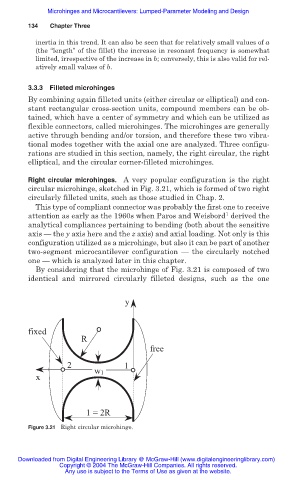
Right circular microhinges. A very popular configuration is the right
circular microhinge, sketched in Fig. 3.21, which is formed of two right
circularly filleted units, such as those studied in Chap. 2.
This type of compliant connector was probably the first one to receive
1
attention as early as the 1960s when Paros and Weisbord derived the
analytical compliances pertaining to bending (both about the sensitive
axis — the y axis here and the z axis) and axial loading. Not only is this
configuration utilized as a microhinge, but also it can be part of another
two-segment microcantilever configuration — the circularly notched
one — which is analyzed later in this chapter.
By considering that the microhinge of Fig. 3.21 is composed of two
identical and mirrored circularly filleted designs, such as the one
y
fixed
R
free
2 1
w1
x
1 = 2R
Figure 3.21 Right circular microhinge.
Downloaded from Digital Engineering Library @ McGraw-Hill (www.digitalengineeringlibrary.com)
Copyright © 2004 The McGraw-Hill Companies. All rights reserved.
Any use is subject to the Terms of Use as given at the website.