
Page 140 - Mechanical design of microresonators _ modeling and applications
P. 140
0-07-145538-8_CH03_139_08/30/05
Microhinges and Microcantilevers: Lumped-Parameter Modeling and Design
Microhinges and Microcantilevers: Lumped-Parameter Modeling and Design 139
3 3
Eb t
k b,e =
2
3
a 2.572b + 24.849bw +4.713w 1 2
1
2
2
+6(2b + w )(4b í 4bw í w ) (3.94)
1
1
1
/ w (4b + w ) arctan 1+4b w 1
/
1
1
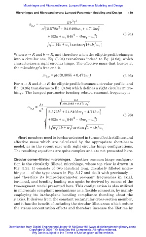
When a ĺ R and b ĺ R, and therefore when the elliptic profile changes
into a circular one, Eq. (3.94) transforms indeed to Eq. (3.83), which
characterizes a right circular hinge. The effective mass that locates at
the microhinge’s free end is
m = ȡta(0.308b +0.471w ) (3.95)
b,e 1
For a ĺ R and b ĺ R the elliptic profile becomes a circular profile, and
Eq. (3.95) transforms to Eq. (3.84) which defines a right circular micro-
hinge. The lumped-parameter bending-related resonant frequency is
Eb
bt ȡ(0.308b + 0.471w )
1
Ȧ =
b,e 2
2
a 2.572b + 24.849bw + 4.713w 2
1 1
(3.96)
2
2
+6(2b + w )(4b í 4bw í w )
1 1 1
/ w (4b + w ) arctan 1+4b w 1
/
1
1
Short members need to be characterized in terms of both stiffness and
effective mass which are calculated by the appropriate short-beam
model, as in the recent case with right circular hinge configurations.
The resulting equations are quite complex and are not presented here.
Circular corner-filleted microhinges. Another common hinge configura-
tion is the circularly filleted microhinge, whose top view is drawn in
Fig. 3.23. It consists of two identical long, circularly filleted micro-
hinges — of the type shown in Fig. 3.17 and dealt with previously —
and therefore its lumped-parameter resonant frequencies in axial,
torsional, and bending loading can again be derived by means of the
two-segment model presented here. This configuration is also utilized
in microscale compliant mechanisms as a flexible connector, by mainly
employing its in-the-plane bending compliance (bending about the
y axis). It derives from the constant rectangular cross-section member,
and it has the benefit of including the circular fillet areas which reduce
the stress concentration effects and therefore increase the lifetime by
Downloaded from Digital Engineering Library @ McGraw-Hill (www.digitalengineeringlibrary.com)
Copyright © 2004 The McGraw-Hill Companies. All rights reserved.
Any use is subject to the Terms of Use as given at the website.