
Page 138 - Mechanical design of microresonators _ modeling and applications
P. 138
0-07-145538-8_CH03_137_08/30/05
Microhinges and Microcantilevers: Lumped-Parameter Modeling and Design
Microhinges and Microcantilevers: Lumped-Parameter Modeling and Design 137
y
elliptic contour
ϕ b
fixed
free
2 1
w1
x
w
x
1 = 2a
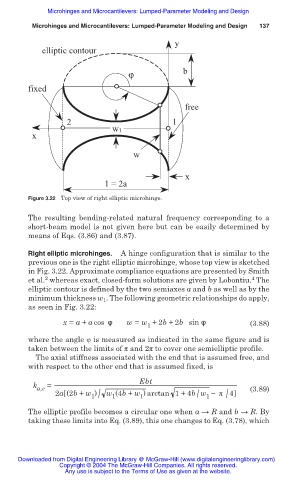
Figure 3.22 Top view of right elliptic microhinge.
The resulting bending-related natural frequency corresponding to a
short-beam model is not given here but can be easily determined by
means of Eqs. (3.86) and (3.87).
Right elliptic microhinges. A hinge configuration that is similar to the
previous one is the right elliptic microhinge, whose top view is sketched
in Fig. 3.22. Approximate compliance equations are presented by Smith
2
4
et al. whereas exact, closed-form solutions are given by Lobontiu. The
elliptic contour is defined by the two semiaxes a and b as well as by the
minimum thickness w 1 . The following geometric relationships do apply,
as seen in Fig. 3.22:
x = a + a cos ́ w = w +2b +2b sin ́ (3.88)
1
where the angle ij is measured as indicated in the same figure and is
taken between the limits of ʌ and 2ʌ to cover one semielliptic profile.
The axial stiffness associated with the end that is assumed free, and
with respect to the other end that is assumed fixed, is
Ebt
k =
a,e (3.89)
1 /
/
/
2a (2b + w ) w (4b + w ) arctan 1+4b w íʌ 4
1
1
1
The elliptic profile becomes a circular one when a ĺ R and b ĺ R. By
taking these limits into Eq. (3.89), this one changes to Eq. (3.78), which
Downloaded from Digital Engineering Library @ McGraw-Hill (www.digitalengineeringlibrary.com)
Copyright © 2004 The McGraw-Hill Companies. All rights reserved.
Any use is subject to the Terms of Use as given at the website.