
Page 141 - Mechanical design of microresonators _ modeling and applications
P. 141
0-07-145538-8_CH03_140_08/30/05
Microhinges and Microcantilevers: Lumped-Parameter Modeling and Design
140 Chapter Three
y
fixed
R
free
2 1
w1
x
l
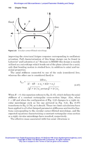
Figure 3.23 Circular corner-filleted microhinge.
improving the structural fatigue response corresponding to oscillatory
actuation. Full characterization of this hinge design can be found in
4
3
Lobontiu and Lobontiu et al. Because in MEMS this design is mainly
utilized as a microhinge which bends out of the plane (about the z axis),
only that bending motion is studied here, in addition to axial and tor-
sional properties.
The axial stiffness connected to one of the ends (considered free,
whereas the other one is considered fixed) is
2Etw 1
k a,e =
2l 4R ʌ w +4(2r + w )
1 1 (3.97)
/ 1+4r w arctan 1+4r w 1
/
/
1
When R ĺ 0, this equation reduces to Eq. (2.45), which defines the axial
stiffness of a constant rectangular cross-section hinge. Also, when
l ĺ 2R and when the configuration of Fig. 3.23 changes to a right cir-
cular microhinge such as the one pictured in Fig. 3.21, Eq. (3.97)
transforms to Eq. (3.78), as it should. These two limit calculations have
been applied to all other lumped-parameter stiffnesses and inertia frac-
tions corresponding to the circular corner-filleted microhinge, and the
expected equations characterizing a constant rectangular cross-section
or a right circular microhinge have resulted, respectively.
The effective mass associated with free axial vibrations is
Downloaded from Digital Engineering Library @ McGraw-Hill (www.digitalengineeringlibrary.com)
Copyright © 2004 The McGraw-Hill Companies. All rights reserved.
Any use is subject to the Terms of Use as given at the website.