
Page 146 - Mechanical design of microresonators _ modeling and applications
P. 146
0-07-145538-8_CH03_145_08/30/05
Microhinges and Microcantilevers: Lumped-Parameter Modeling and Design
Microhinges and Microcantilevers: Lumped-Parameter Modeling and Design 145
UȦ
î 5 >P@
Z >P@
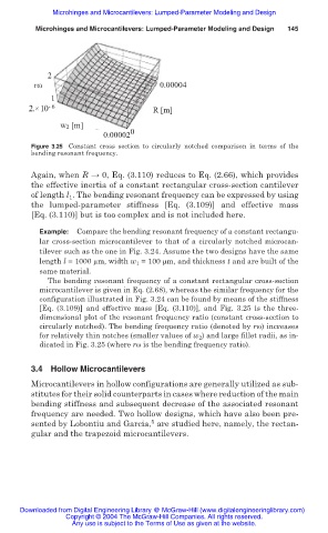
Figure 3.25 Constant cross section to circularly notched comparison in terms of the
bending resonant frequency.
Again, when R ĺ 0, Eq. (3.110) reduces to Eq. (2.66), which provides
the effective inertia of a constant rectangular cross-section cantilever
of length l . The bending resonant frequency can be expressed by using
1
the lumped-parameter stiffness [Eq. (3.109)] and effective mass
[Eq. (3.110)] but is too complex and is not included here.
Example: Compare the bending resonant frequency of a constant rectangu-
lar cross-section microcantilever to that of a circularly notched microcan-
tilever such as the one in Fig. 3.24. Assume the two designs have the same
length l = 1000 m, width w 1 = 100 m, and thickness t and are built of the
same material.
The bending resonant frequency of a constant rectangular cross-section
microcantilever is given in Eq. (2.68), whereas the similar frequency for the
configuration illustrated in Fig. 3.24 can be found by means of the stiffness
[Eq. (3.109)] and effective mass [Eq. (3.110)], and Fig. 3.25 is the three-
dimensional plot of the resonant frequency ratio (constant cross-section to
circularly notched). The bending frequency ratio (denoted by rȦ) increases
for relatively thin notches (smaller values of w 2 ) and large fillet radii, as in-
dicated in Fig. 3.25 (where rȦ is the bending frequency ratio).
3.4 Hollow Microcantilevers
Microcantilevers in hollow configurations are generally utilized as sub-
stitutes for their solid counterparts in cases where reduction of the main
bending stiffness and subsequent decrease of the associated resonant
frequency are needed. Two hollow designs, which have also been pre-
5
sented by Lobontiu and Garcia, are studied here, namely, the rectan-
gular and the trapezoid microcantilevers.
Downloaded from Digital Engineering Library @ McGraw-Hill (www.digitalengineeringlibrary.com)
Copyright © 2004 The McGraw-Hill Companies. All rights reserved.
Any use is subject to the Terms of Use as given at the website.