Page 147 - Mechanical design of microresonators _ modeling and applications
P. 147

0-07-145538-8_CH03_146_08/30/05


                                   Microhinges and Microcantilevers: Lumped-Parameter Modeling and Design

                              146   Chapter Three


                                                 w2              l2
                                        w1


                                              11
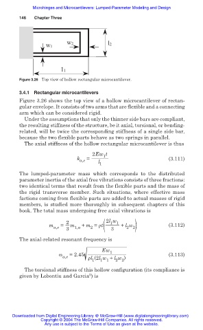
                              Figure 3.26 Top view of hollow rectangular microcantilever.

                              3.4.1  Rectangular microcantilevers
                              Figure 3.26 shows the top view of a hollow microcantilever of rectan-
                              gular envelope. It consists of two arms that are flexible and a connecting
                              arm which can be considered rigid.
                                Under the assumptions that only the thinner side bars are compliant,
                              the resulting stiffness of the structure, be it axial, torsional, or bending-
                              related, will be twice the corresponding stiffness of a single side bar,
                              because the two flexible parts behave as two springs in parallel.
                                The axial stiffness of the hollow rectangular microcantilever is thus

                                                          2Ew t
                                                               1
                                                    k a,e  =                            (3.111)
                                                             l
                                                             1
                              The  lumped-parameter mass which corresponds to the distributed
                              parameter inertia of the axial free vibrations consists of three fractions:
                              two identical terms that result from the flexible parts and the mass of
                              the rigid transverse member.  Such  situations, where effective mass
                              factions coming from flexible parts are added to actual masses of rigid
                              members, is studied more thoroughly in subsequent chapters of this
                              book. The total mass undergoing free axial vibrations is

                                                                        2 2)
                                                          2 (
                                                2               2l w
                                                                 1 1
                                          m a,e  =  3  m 1,a  + m = ȡt  3  + l w        (3.112)
                              The axial-related resonant frequency is
                                                              Ew 1
                                             Ȧ    =2.45                                 (3.113)
                                               a,e       ȡl (2l w + l w )
                                                          1  1 1   2 2
                                The torsional stiffness of this hollow configuration (its compliance is
                                                         5
                              given by Lobontiu and Garcia ) is


                           Downloaded from Digital Engineering Library @ McGraw-Hill (www.digitalengineeringlibrary.com)
                                      Copyright © 2004 The McGraw-Hill Companies. All rights reserved.
                                        Any use is subject to the Terms of Use as given at the website.
   142   143   144   145   146   147   148   149   150   151   152