Page 149 - Mechanical design of microresonators _ modeling and applications
P. 149

0-07-145538-8_CH03_148_08/30/05


                                   Microhinges and Microcantilevers: Lumped-Parameter Modeling and Design

                              148   Chapter Three


                                  5
                                                                     0.5
                              r ω
                                   1
                              0.00001                              c2


                                            c1
                                                           0.00001
                                                        0.5
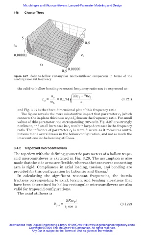
                              Figure 3.27 Solid-to-hollow rectangular microcantilever comparison in terms  of the
                              bending resonant frequency.


                                the solid-to-hollow bending resonant frequency ratio can be expressed as
                                                  Ȧ s         33c +70c 2
                                                                 1
                                             r =  Ȧ  =0.174                              (3.121)
                                              Ȧ
                                                   h              c 1
                                and Fig. 3.27 is the three-dimensional plot of this frequency ratio.
                                  The figure reveals the more substantive impact that parameter c 1  (which
                                connects the in-plane thickness w 1  to l 2 ) has on the frequency ratio. For small
                                values of this parameter, the corresponding curves in Fig. 3.27 are strongly
                                nonlinear, and small increases in c 1  result in large decreases in the frequency
                                ratio. The influence of parameter c 2  is more discrete as it measures contri-
                                butions to the overall mass in the hollow configuration, and not so much the
                                interventions in the bending stiffness.


                              3.4.2  Trapezoid microcantilevers
                              The top view with the defining geometric parameters of a hollow trape-
                              zoid microcantilever is sketched in Fig. 3.28. The assumption is also
                              made that the side arms are flexible, whereas the transverse connecting
                              arm is rigid. Compliances in axial loading, torsion, and bending are
                              provided for this configuration by Lobontiu and Garcia. 5
                                In calculating the significant resonant  frequencies,  the  inertia
                              fractions corresponding to axial, torsion, and bending vibrations that
                              have been determined for hollow rectangular microcantilevers are also
                              valid for trapezoid configurations.
                                The axial stiffness is

                                                          2Ew t
                                                               1
                                                    k   =                               (3.122)
                                                     a,e  l cos Į
                                                          1


                           Downloaded from Digital Engineering Library @ McGraw-Hill (www.digitalengineeringlibrary.com)
                                      Copyright © 2004 The McGraw-Hill Companies. All rights reserved.
                                        Any use is subject to the Terms of Use as given at the website.
   144   145   146   147   148   149   150   151   152   153   154