
Page 154 - Mechanical design of microresonators _ modeling and applications
P. 154
0-07-145538-8_CH03_153_08/30/05
Microhinges and Microcantilevers: Lumped-Parameter Modeling and Design
Microhinges and Microcantilevers: Lumped-Parameter Modeling and Design 153
whereas the distance corresponding to the geometric symmetry center
of the compound cross section is
n
z i
i =1 (3.141)
z = n
C
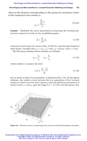
Example: Establish the errors generated in calculating the torsional me-
chanical moment of inertia by the simplified equation
n
Ҡ
J = J ti (3.142)
t
i =1
instead of calculating it by means of Eq. (3.138) for a multimorph formed of
three layers. Consider that ȡ 2 = 1.1ȡ 1 , ȡ 3 = 0.9ȡ 1 , w = 50 Ím, and t 1 = 3 Ím.
The following nondimensional amounts are utilized:
t 2 t 3
c = c = (3.143)
2 t 1 3 t 1
which enable is to express the error
J í J t Ҡ
t
eJ = (3.144)
t Ҡ
J t
just in terms of these two parameters, as plotted in Fig. 3.31. As this figure
indicates, the relative errors between the two expressions of the torsional
moment of inertia are less than 4 percent when the thickness parameters of
layers 2 and 3, c 2 and c 3 , span the range 0.5 ĺ 1.5. For very thin layers, this
4
e J 1.5
t
2
0.5
c 3
c 2
0.5
1.5
Figure 3.31 Relative errors in expressing the torsional mechanical moment of inertia.
Downloaded from Digital Engineering Library @ McGraw-Hill (www.digitalengineeringlibrary.com)
Copyright © 2004 The McGraw-Hill Companies. All rights reserved.
Any use is subject to the Terms of Use as given at the website.