
Page 159 - Mechanical design of microresonators _ modeling and applications
P. 159
0-07-145538-8_CH03_158_08/30/05
Microhinges and Microcantilevers: Lumped-Parameter Modeling and Design
158 Chapter Three
patch
lp
tp
substrate 1 1
1 t1
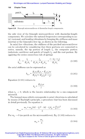
Figure 3.35 Bimorph microcantilever of dissimilar-length components.
the side view of the bimorph microcantilever with dissimilar-length
components. We calculate the natural frequencies corresponding to ax-
ial, torsional, and bending vibrations by lumping the stiffness and mass
(inertia) at the bimorph’s free tip, as shown in the following.
In axial free vibrations, the stiffness of the patched microcantilever
can be calculated by considering that three portions are connected in
series, namely, the tip portion of length l , the composite portion
1
(substrate cantilever and patch) of length l p , and the root portion. By
applying the series connection rule of springs
1 l 1 l p l í (l + l )
p
1
k a,e = E A 1 + E A + E A p + E A 1 (3.160)
1
1
1
p
1
the axial stiffness can be expressed as
E t (E t + E t )w
p p
1 1
1 1
k = (3.161)
a,e E t l + E t (l í l )
1 1 p p p
Equation (3.161) reduces to
E t w
1 1
k = l (3.162)
a
when t p ĺ 0, which is the known relationship for a one-component
microrod.
The lumped mass which corresponds to axial vibrations is calculated
by means of Rayleigh’s principle, a procedure that has been discussed
in detail previously. Its equation is
2
2
m + m 3(l í l ) í 3(l í l )l + l p / l 2
1 p
p
1
1
m = (3.163)
a,e
3
For m p ĺ 0 (no patch on the microcantilever), Eq. (3.163) reduces to
m 1
m = (3.164)
a 3
Downloaded from Digital Engineering Library @ McGraw-Hill (www.digitalengineeringlibrary.com)
Copyright © 2004 The McGraw-Hill Companies. All rights reserved.
Any use is subject to the Terms of Use as given at the website.