
Page 164 - Mechanical design of microresonators _ modeling and applications
P. 164
0-07-145538-8_CH03_163_08/30/05
Microhinges and Microcantilevers: Lumped-Parameter Modeling and Design
Microhinges and Microcantilevers: Lumped-Parameter Modeling and Design 163
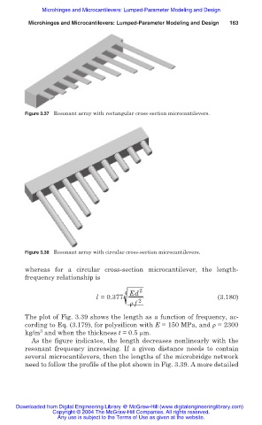
Figure 3.37 Resonant array with rectangular cross-section microcantilevers.
Figure 3.38 Resonant array with circular cross-section microcantilevers.
whereas for a circular cross-section microcantilever, the length-
frequency relationship is
4 Ed 2
l = 0.377 (3.180)
ȡ f 2
The plot of Fig. 3.39 shows the length as a function of frequency, ac-
cording to Eq. (3.179), for polysilicon with E = 150 MPa, and ȡ = 2300
3
kg/m and when the thickness t = 0.5 m.
As the figure indicates, the length decreases nonlinearly with the
resonant frequency increasing. If a given distance needs to contain
several microcantilevers, then the lengths of the microbridge network
need to follow the profile of the plot shown in Fig. 3.39. A more detailed
Downloaded from Digital Engineering Library @ McGraw-Hill (www.digitalengineeringlibrary.com)
Copyright © 2004 The McGraw-Hill Companies. All rights reserved.
Any use is subject to the Terms of Use as given at the website.