
Page 155 - Mechanical design of microresonators _ modeling and applications
P. 155
0-07-145538-8_CH03_154_08/30/05
Microhinges and Microcantilevers: Lumped-Parameter Modeling and Design
154 Chapter Three
thickness range is quite extended, and therefore errors smaller than the
maximum value shown on the plot of Fig. 3.31 can be expected.
The torsional resonant frequency can therefore be written as
k t,e n G I
i ti
Ȧ = = 3 (3.145)
t,e m J l
t,e i =1 t
For a bimorph (two-component sandwiched microcantilever), the tor-
sional resonant frequency becomes
3 3
2 3 G t + G t
1 1
2 2
Ȧ t,e = l 2 2 2 2 2 2 (3.146)
ȡ t (t +3t + w ) + ȡ t (t +3t + w )
1 1 1 2 2 2 2 1
When t 2 ĺ 0, Eq. (3.146) simplifies to
2 3t 1 G 1 3k t1
Ȧ = = (3.147)
t l ȡ (t + w ) J t1
2
2
1 1
which is the known torsion-related resonant frequency of a homoge-
neous (one-component) microbar.
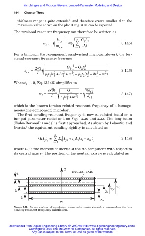
The first bending resonant frequency is now calculated based on a
lumped-parameter model and on Figs. 3.30 and 3.32. The long-beam
(Euler-Bernoulli) model is first approached. As shown by Lobontiu and
5
Garcia, the equivalent bending rigidity is calculated as
n
(EI ) = E I + z A (z í z ) (3.148)
y e i yi i i i N
i =1
where I yi is the moment of inertia of the ith component with respect to
its central axis y . The position of the neutral axis z is calculated as
i
N
z
neutral axis
t1
z1
zN
ti
zi
tn
w zn
Figure 3.32 Cross section of sandwich beam with main geometry parameters for the
bending resonant frequency calculation.
Downloaded from Digital Engineering Library @ McGraw-Hill (www.digitalengineeringlibrary.com)
Copyright © 2004 The McGraw-Hill Companies. All rights reserved.
Any use is subject to the Terms of Use as given at the website.