
Page 125 - Mechanical Engineer's Data Handbook
P. 125
114 MECHANICAL ENGINEER’S DATA HANDBOOK
3.7 Steam turbines
This section deals with the two main types of steam ing blades are of similar form, consisting of converging
turbine, the ‘impulse turbine’ and the ‘impulse-reac- passages to give a pressure drop in each case. In the
tion turbine’. The theory is given for a single-stage case of 50% reaction (Parson’s turbine) the enthalpy
impulse turbine and velocity compounded impulse drop is the same for both fixed and moving blades.
turbine. Stage efficiency, overall efficiency and the reheat
In the impulse-reaction turbine the fixed and mov- factor are defined.
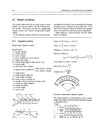
3.7. I Impulse turbine Power P = mC2p(cos a -p)( 1 + k)
C
Single-stage impulse turbine where: p=b and Cb=2nR,N
c
Symbols used: Efficiency q = 2p(cos o! - p)( 1 + k)
C = nozzle velocity
C, = blade velocity Maximum efficiency
C, = axial velocity
p=ratio of blade to nozzle velocity
8, =blade inlet angle
/I, = blade outlet angle (in this case j1 =/Iz) Axial thrust T, = mC( 1 - k) sin a
a= nozzle angle CaA
m=mass flow rate of steam Mass flow rate m=-
outlet relative velocity V
k =blade friction coefficient = nR,Oh
inlet relative velocity Nozzle area A=-
P = stage power 180
4 =stage diagram efficiency
T, =axial thrust on blades
R, =mean radius of nozzle arc
v=specific volume of steam at nozzle outlet
0 =nozzle arc angle (degrees)
N=speed of rotation
h = nozzle height
A =nozzle area
Pressure compounded impulse turbine
The steam pressure is broken down in two or more
stages. Each stage may be analysed in the same manner
as described above.
Pressure
L2??3Glca