
Page 122 - Mechanical Engineer's Data Handbook
P. 122
THERMODYNAMICS AND HEAT TRANSFER 111
3.5 Flow through nozzles
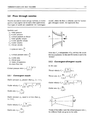
Nozzles are used in steam and gas turbines, in rocket nozzle’, where the flow is subsonic; and the ‘conver-
motors, in jet engines and in many other applications. gent divergent nozzle’, for supersonic flow.
Two types of nozzle are considered: the ‘convergent
Symbols used:
p = inlet pressure
p, =outlet pressure
p, =critical pressure at throat
u I = inlet specific volume
u2 =outlet specific volume
C, =outlet velocity
C, = throat velocity
P2
r = pressure ratio = -
P1
Note that C, is independent of p2 and that the nozzle
P
rc =critical pressure ratio = 2 flow is a maximum. In this case the nozzle is said to be
P1 ‘choked’.
A, =outlet area
A, = throat area
n =index of expansion 3.5.2 Convergent-divergent nozzle
h=mass flow rate
In this case:
Critical pressure ratio r, = -
(n: I)(*) Throat velocity C, = /m n+ 1
3.5. I Convergent nozzle Throat area A, = -, mu, r, =
CArJ
Outlet pressure p2 greater than p,. i.e. r>r,
Outlet velocity C,= /= -
Outlet velocity C,= /= -
mV
Outlet area A,=L
mv 1 C,(rf
Outlet area A,=7
C,(r).
Outlet pressure p2 equal to or less than pc,
i.e. r<r,
mu
Outlet area A,=+ Values of the index n and the critical pressure ratio r,
C*(rF for different fluids are given in the table.