
Page 126 - Mechanical Engineer's Data Handbook
P. 126
THERMODYNAMICS AND HEAT TRANSFER 115
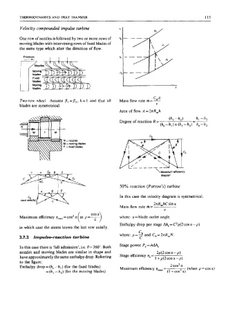
Velocity compounded impulse turbine
One row of nozzles is followed by two or more rows of
moving blades with intervening rows of fixed blades of
the same type which alter the direction of flow.
Ce.A
Two-row wheel Assume PI = P2, k = 1 and that all Mass flow rate m=-
blades are symmetrical. V
Area of flow A=2nRmh
\Maximom efficiency
diagram
50% reaction (Parson’s) turbine
c, In this case the velocity diagram is symmetrical.
(exit velocitv)
2nR,hC sin a
Mass flow rate m= V
Maximum efficiency vmax =cosz a (at p = y) where: a= blade outlet angle.
Enthalpy drop per stage Ahs = C’p(2 cos a - p)
in which case the steam leaves the last row axially.
Cb
where: p=- and Cb=2nR,N.
3.7.2 Impulse-reaction turbine C
In this case there is ‘full admission’, i.e. e= 360”. Both Stage power P,=mAh,
nozzles and moving blades are similar in shape and 2p(2 cos a - p)
have approximately the same enthalpy drop. Referring Stage efficiency q, = 1 +p(2cosa-p)
to the figure:
Enthalpy drop = (h, - h,) (for the fixed blades) Maximum efficiency qmX = 2 cos2 a (when p =cos a)
= (h, -h2) (for the moving blades) (1 + cos2 .)