
Page 131 - Mechanical Engineer's Data Handbook
P. 131
120 MECHANICAL ENGINEER’S DATA HANDBOOK
(IY-
1)
Efficiency = 1 -
(/3-1)yrY-l
V V
where: r=A and /3=”. (‘cut-off ratio)
02 02
W=c,(T,- T2)-c,(T4- T,)
Q = cp( T3 - TZ )
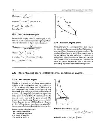
3.9.5 Dual combustion cycle
Modern diesel engines follow a similar cycle to this V
ideal one. In this case combustion takes place partly at
constant volume and partly at constant pressure. 3.9.6 Practical engine cycles
(kPY - 1 ) In actual engines the working substance is air only in
Efficiency q = 1 -
C(k-l)+(B-l)yk]rY-l the induction and compression strokes. During expan-
sion and exhaust the working substance consists of the
products of combustion with different properties to
air. In addition, the wide variations in temperature
and pressure result in variation in the thermal proper-
ties. Another factor is ‘dissociation’ which results in a
lower maximum temperature than is assumed in
elementary treatment of the combustion process.
3.10 Reciprocating spark ignition internal combustion engines
3. IO. I Four-stroke engine
The charge of air and fuel is induced into the engine
cylinder as the piston moves from top dead centre
(TDC) to bottom dead centre (BDC). The charge is
then compressed and ignited by the sparking plug
before TDC producing high pressure and temperature
at about TDC. The gas expands and work is produced
as the piston moves to BDC. A little before BDC the
exhaust valve opens and the gases exhaust. The
process is completed during the next stroke. A typical
‘timing diagram’ (section 3.10.3) and the p-v diagram
are shown. Formulae are given for power, mean effec-
tive pressure, efficiency and specific fuel consumption.
Pressure-volume (p-v) diagram: Indicated mean effective pressure
K
A=area of power loop pi = (A - B) - (N mm - ’)
B=area of pumping loop Ld
L, = length of diagram n
K =indicator constant Indicated power Pi =piApLN - (watts)
2